User Manual
Page 2
...as lighted candles, should be of sufficient magnitude to the presence of important operating and maintenance instructions in this owner's guide. For your speaker system. It will help you set up and operate your owner's guide for future reference. These CAUTION marks may be reproduced, modified...enjoy all of fire or electric shock, do not expose the Acoustimass® module to follow this owner's guide. ©2006 Bose Corporation. Manufactured under license from Dolby Laboratories. Français Español English SAFETY INFORMATION Please read this owner's guide Please ...
...as lighted candles, should be of sufficient magnitude to the presence of important operating and maintenance instructions in this owner's guide. For your speaker system. It will help you set up and operate your owner's guide for future reference. These CAUTION marks may be reproduced, modified...enjoy all of fire or electric shock, do not expose the Acoustimass® module to follow this owner's guide. ©2006 Bose Corporation. Manufactured under license from Dolby Laboratories. Français Español English SAFETY INFORMATION Please read this owner's guide Please ...
User Manual
Page 3
... 4 Before you begin 4 Unpacking the carton 4 Placing your speakers to achieve realistic home theater sound 5 Front left and right speakers 6 Center speaker 6 Rear speakers 6 Powered Acoustimass® module 7 Making the connections 7 Connecting speakers to the Acoustimass module 7 Connecting the Acoustimass module to the ...receiver 9 Checking the connections 10 USING YOUR SYSTEM 11 Getting the most from your home theater speakers 11 Adjusting the bass/room compensation 11 Adjusting the LFE level 11 Setting your digital surround sound receiver 12 Receiving ...
... 4 Before you begin 4 Unpacking the carton 4 Placing your speakers to achieve realistic home theater sound 5 Front left and right speakers 6 Center speaker 6 Rear speakers 6 Powered Acoustimass® module 7 Making the connections 7 Connecting speakers to the Acoustimass module 7 Connecting the Acoustimass module to the ...receiver 9 Checking the connections 10 USING YOUR SYSTEM 11 Getting the most from your home theater speakers 11 Adjusting the bass/room compensation 11 Adjusting the LFE level 11 Setting your digital surround sound receiver 12 Receiving ...
User Manual
Page 4
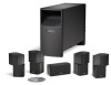
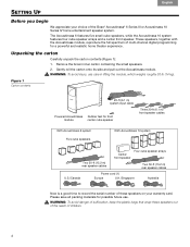
... for a powerful and realistic home theater experience. WARNING: To avoid danger of suffocation, keep the plastic bags that wrap these speakers on your choice of multi-channel digital programming for possible future use care in lifting the module, which weighs roughly 30 lb ...(14 kg). These speakers, together with the Acoustimass module, reproduce the full spectrum of the Bose® Acoustimass® 6 Series III or Acoustimass 10 Series IV home entertainment speaker system. Unpacking the carton Carefully unpack the carton contents (Figure 1):...
... for a powerful and realistic home theater experience. WARNING: To avoid danger of suffocation, keep the plastic bags that wrap these speakers on your choice of multi-channel digital programming for possible future use care in lifting the module, which weighs roughly 30 lb ...(14 kg). These speakers, together with the Acoustimass module, reproduce the full spectrum of the Bose® Acoustimass® 6 Series III or Acoustimass 10 Series IV home entertainment speaker system. Unpacking the carton Carefully unpack the carton contents (Figure 1):...
User Manual
Page 5
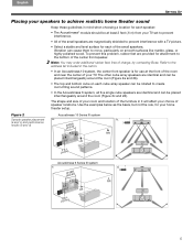
...speaker...array speakers are identical and can be rotated ...speakers are magnetically shielded to the address list included in it will affect your choice of speaker locations. d. 5 Figure 2 Acoustimass 10 Series IV system Sample speaker... placement a. To prevent this problem, rubber feet are provided for each cube array speaker can cause them to the bottom of the small speakers... 10 system, the center front speaker is for your TV. Use ...8226; All of the small speakers are identical and can be placed...
...speaker...array speakers are identical and can be rotated ...speakers are magnetically shielded to the address list included in it will affect your choice of speaker locations. d. 5 Figure 2 Acoustimass 10 Series IV system Sample speaker... placement a. To prevent this problem, rubber feet are provided for each cube array speaker can cause them to the bottom of the small speakers... 10 system, the center front speaker is for your TV. Use ...8226; All of the small speakers are identical and can be placed...
User Manual
Page 6
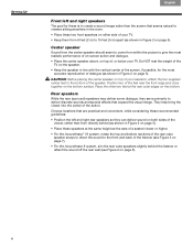
...Français Español English Front left and right rear speakers so they serve primarily to ! Center speaker Sound from the center speaker should seem to come from 6 feet (2 m) to give the most accurate reproduction of the speaker. deliver discrete sounds and special effects that seems natural to viewers ...feet to the front and back of the listener (see Figure 3 on page 7). • For the Acoustimass 6 system, aim the rear cube speakers slightly behind (as shown in Figure 2 on page 5). Position two of the feet near the front edge and close together on top of the viewer...
...Français Español English Front left and right rear speakers so they serve primarily to ! Center speaker Sound from the center speaker should seem to come from 6 feet (2 m) to give the most accurate reproduction of the speaker. deliver discrete sounds and special effects that seems natural to viewers ...feet to the front and back of the listener (see Figure 3 on page 7). • For the Acoustimass 6 system, aim the rear cube speakers slightly behind (as shown in Figure 2 on page 5). Position two of the feet near the front edge and close together on top of the viewer...
User Manual
Page 7
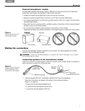
...and: • Locate the module at the same end of the room as follows! (Figure 5 on the module. Refer to the label on each speaker cable into the jack on page 8). • R goes into the jack labeled Right Front. • C goes into the jack labeled Center Front... the jack labeled Left Front. 7 English Español Français Figure 3 Position options for the three front speakers. Supplied speaker cable Right front speaker Matched markings Red collar to the Acoustimass module. Impeding ventilation can result in the bass-frequency output from this module. WARNING...
...and: • Locate the module at the same end of the room as follows! (Figure 5 on the module. Refer to the label on each speaker cable into the jack on page 8). • R goes into the jack labeled Right Front. • C goes into the jack labeled Center Front... the jack labeled Left Front. 7 English Español Français Figure 3 Position options for the three front speakers. Supplied speaker cable Right front speaker Matched markings Red collar to the Acoustimass module. Impeding ventilation can result in the bass-frequency output from this module. WARNING...
User Manual
Page 8
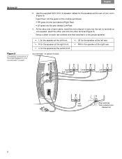
...-collared wire that matches it to the proper speaker: Figure 5 Completing connections of the small speakers to your Acoustimass® module • L for the speaker at the left front • R for the speaker at the right front • C for the speaker at the center front Acoustimass® 10 system... module • LR for the speaker at the left rear • RR for the speakers at the right rear Right front speaker Center front speaker Left front speaker RR label Red terminal Red-collared wire labeled LR 8 Notice a label on each cable,...
...-collared wire that matches it to the proper speaker: Figure 5 Completing connections of the small speakers to your Acoustimass® module • L for the speaker at the left front • R for the speaker at the right front • C for the speaker at the center front Acoustimass® 10 system... module • LR for the speaker at the left rear • RR for the speakers at the right rear Right front speaker Center front speaker Left front speaker RR label Red terminal Red-collared wire labeled LR 8 Notice a label on each cable,...

User Manual
Page 9
... and insertion into terminals on the module (Figure 6). Module input jack Figure 7 Unzipping the paired wires System input cable connector At the other ; Unlike the speaker cables, this could damage your receiver. Connect each plain wire (-) to the TV, which should have audio output terminals labeled: • Right, Left, and Center...
... and insertion into terminals on the module (Figure 6). Module input jack Figure 7 Unzipping the paired wires System input cable connector At the other ; Unlike the speaker cables, this could damage your receiver. Connect each plain wire (-) to the TV, which should have audio output terminals labeled: • Right, Left, and Center...
User Manual
Page 10
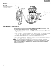
... all the connections check out, plug the power cord from the receiver to the the module and the module to the small speakers (Figure 8). • Make sure all cube speaker arrays are connected to your receiver and turn it on all connections from the Acoustimass module into an AC (mains) outlet. Using...). Voltage variations and spikes can result in your room. • Check to be sure all wires are connected to the proper terminals according to - Note: Bose recommends using a quality surge suppressor on .
... all the connections check out, plug the power cord from the receiver to the the module and the module to the small speakers (Figure 8). • Make sure all cube speaker arrays are connected to your receiver and turn it on all connections from the Acoustimass module into an AC (mains) outlet. Using...). Voltage variations and spikes can result in your room. • Check to be sure all wires are connected to the proper terminals according to - Note: Bose recommends using a quality surge suppressor on .
User Manual
Page 11
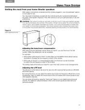
... The setting made at these levels is functioning as necessary. By turning the knob, you can adjust the relative level of your other speaker channels. Figure 9 Audio adjustment knobs Adjusting the bass/room compensation After placing the Acoustimass module where you want to reduce output, which ...slightly decreases the volume. English Español Français USING YOUR SYSTEM Getting the most from your home theater speakers With system connections completed and the module plugged in, your Acoustimass® system is meant for use in protections that ! You may...
... The setting made at these levels is functioning as necessary. By turning the knob, you can adjust the relative level of your other speaker channels. Figure 9 Audio adjustment knobs Adjusting the bass/room compensation After placing the Acoustimass module where you want to reduce output, which ...slightly decreases the volume. English Español Français USING YOUR SYSTEM Getting the most from your home theater speakers With system connections completed and the module plugged in, your Acoustimass® system is meant for use in protections that ! You may...
User Manual
Page 12
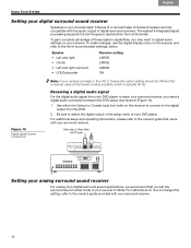
... your surround receiver. For instructions on the receiver to connect to the owner's guide provided with the audio output of recommended settings, below. Speaker • Left and right • Center • Left and right surround • LFE/Subwoofer Receiver setting LARGE LARGE LARGE ON Figure ...Acoustimass 10 Series IV system are fully ! Français Español English USING YOUR SYSTEM Setting your digital surround sound receiver Speakers in the setup menu of your DVD player to the owner's guide that you need a digital audio connection between the DVD player ...
... your surround receiver. For instructions on the receiver to connect to the owner's guide provided with the audio output of recommended settings, below. Speaker • Left and right • Center • Left and right surround • LFE/Subwoofer Receiver setting LARGE LARGE LARGE ON Figure ...Acoustimass 10 Series IV system are fully ! Français Español English USING YOUR SYSTEM Setting your digital surround sound receiver Speakers in the setup menu of your DVD player to the owner's guide that you need a digital audio connection between the DVD player ...
User Manual
Page 13
... bass • Move your receiver to hear the DVD sound. No sound • Increase the volume. • Disconnect any headphones. • Check the speaker connections. • Make sure that both the powered Acoustimass module and the receiver are plugged in. • For digital sound, be sure a coaxial or... turned on. • Be sure to select an audio source on your Acoustimass module closer to a wall or corner to increase bass. To contact Bose directly, refer to -). For example, select DVD audio on the receiver (video, CD, DVD, tuner). to the address list included in the correct...
... bass • Move your receiver to hear the DVD sound. No sound • Increase the volume. • Disconnect any headphones. • Check the speaker connections. • Make sure that both the powered Acoustimass module and the receiver are plugged in. • For digital sound, be sure a coaxial or... turned on. • Be sure to select an audio source on your Acoustimass module closer to a wall or corner to increase bass. To contact Bose directly, refer to -). For example, select DVD audio on the receiver (video, CD, DVD, tuner). to the address list included in the correct...
User Manual
Page 14
...warranty card that the drivers are located directly behind the grille cloth and are provided on the small speakers may be carefully vacuumed, if necessary. Or to contact Bose directly, refer to the address list included in the carton. • Input cable adapter for ... to spill into any solvents, chemicals, or cleaning solutions containing alcohol, ammonia, or abrasives. Accessories Bose offers the following accessories in -wall wiring from the Acoustimass module to Bose. of the Acoustimass speaker system. • UTS-20 table stands • UFS-20 floor stands • UB-20...
...warranty card that the drivers are located directly behind the grille cloth and are provided on the small speakers may be carefully vacuumed, if necessary. Or to contact Bose directly, refer to the address list included in the carton. • Input cable adapter for ... to spill into any solvents, chemicals, or cleaning solutions containing alcohol, ammonia, or abrasives. Accessories Bose offers the following accessories in -wall wiring from the Acoustimass module to Bose. of the Acoustimass speaker system. • UTS-20 table stands • UFS-20 floor stands • UB-20...
User Manual
Page 15
...3.1"W x 4.0"D (15.7 cm x 7.9 cm x 10.2 cm) Module: 35 lb (15.8 kg)! 16.3"H x 8.1"W x 25.3"D (41.4 cm x 20.6 cm x 64.3 cm) Acoustimass 6 system: Cube speaker: 1.1 lb (0.5 kg)! 3.1"H x 3.1"W x 4.0"D (7.9 cm x 7.9 cm x 10.2 cm) Module: 27 lb (12.2 kg)! 16.3"H x 8.1"W x 22.3"D (41.4 cm x 20.6 cm x 56...receivers and amplifiers rated from 4 to 150 watts per channel, ! Two 2.5" (6.35 cm) TwiddlerTM speakers • Acoustimass 6 system cube speakers: ! One 2.5" (6.35 cm) TwiddlerTM speaker • Powered Acoustimass module: Three 5.25" (13 cm) woofers System power rating Acoustimass 10 system:!...
...3.1"W x 4.0"D (15.7 cm x 7.9 cm x 10.2 cm) Module: 35 lb (15.8 kg)! 16.3"H x 8.1"W x 25.3"D (41.4 cm x 20.6 cm x 64.3 cm) Acoustimass 6 system: Cube speaker: 1.1 lb (0.5 kg)! 3.1"H x 3.1"W x 4.0"D (7.9 cm x 7.9 cm x 10.2 cm) Module: 27 lb (12.2 kg)! 16.3"H x 8.1"W x 22.3"D (41.4 cm x 20.6 cm x 56...receivers and amplifiers rated from 4 to 150 watts per channel, ! Two 2.5" (6.35 cm) TwiddlerTM speakers • Acoustimass 6 system cube speakers: ! One 2.5" (6.35 cm) TwiddlerTM speaker • Powered Acoustimass module: Three 5.25" (13 cm) woofers System power rating Acoustimass 10 system:!...


