User Manual
Page 2
... name Dealer phone Purchase date Please keep your owner's guide for future reference. All rights reserved. 2 It will help you set up and operate your speaker system. CAUTION: To prevent electric shock, match wide blade of the Acoustimass module. These CAUTION marks may be reproduced, modified, distributed, or otherwise used without.... Français Español English SAFETY INFORMATION Please read this owner's guide Please take the time to follow this owner's guide. ©2006 Bose Corporation.
... name Dealer phone Purchase date Please keep your owner's guide for future reference. All rights reserved. 2 It will help you set up and operate your speaker system. CAUTION: To prevent electric shock, match wide blade of the Acoustimass module. These CAUTION marks may be reproduced, modified, distributed, or otherwise used without.... Français Español English SAFETY INFORMATION Please read this owner's guide Please take the time to follow this owner's guide. ©2006 Bose Corporation.
User Manual
Page 3
... 4 Before you begin 4 Unpacking the carton 4 Placing your speakers to achieve realistic home theater sound 5 Front left and right speakers 6 Center speaker 6 Rear speakers 6 Powered Acoustimass® module 7 Making the connections 7 Connecting speakers to the Acoustimass module 7 Connecting the Acoustimass module to the ...receiver 9 Checking the connections 10 USING YOUR SYSTEM 11 Getting the most from your home theater speakers 11 Adjusting the bass/room compensation 11 Adjusting the LFE level 11 Setting your digital surround sound receiver 12 Receiving ...
... 4 Before you begin 4 Unpacking the carton 4 Placing your speakers to achieve realistic home theater sound 5 Front left and right speakers 6 Center speaker 6 Rear speakers 6 Powered Acoustimass® module 7 Making the connections 7 Connecting speakers to the Acoustimass module 7 Connecting the Acoustimass module to the ...receiver 9 Checking the connections 10 USING YOUR SYSTEM 11 Getting the most from your home theater speakers 11 Adjusting the bass/room compensation 11 Adjusting the LFE level 11 Setting your digital surround sound receiver 12 Receiving ...
User Manual
Page 4
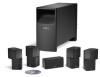
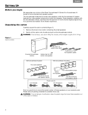
... U.S./Canada Power cord (1) Europe U.K./Singapore Australia Now is a good time to record the serial number of these speakers on your choice of the Bose® Acoustimass® 6 Series III or Acoustimass 10 Series IV home entertainment speaker system. Figure 1 Carton contents 20-ft (6.1 m) system input cable Powered Acoustimass Rubber feet for a powerful and...
... U.S./Canada Power cord (1) Europe U.K./Singapore Australia Now is a good time to record the serial number of these speakers on your choice of the Bose® Acoustimass® 6 Series III or Acoustimass 10 Series IV home entertainment speaker system. Figure 1 Carton contents 20-ft (6.1 m) system input cable Powered Acoustimass Rubber feet for a powerful and...
User Manual
Page 5
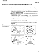
..., rubber feet are magnetically shielded to prevent interference with a TV picture. • Select a stable and level surface for each of the small speakers. The shape and size of your room and location of the furniture in it will affect your TV set to prevent interference. • All of...(b and d) Acoustimass 6 Series III system c. Refer to the address list included in the carton. • In an Acoustimass 10 system, the center front speaker is for use at least 2 feet (.6 m) from your choice of charge, by contacting Bose. Note: You may order additional rubber feet, free of...
..., rubber feet are magnetically shielded to prevent interference with a TV picture. • Select a stable and level surface for each of the small speakers. The shape and size of your room and location of the furniture in it will affect your TV set to prevent interference. • All of...(b and d) Acoustimass 6 Series III system c. Refer to the address list included in the carton. • In an Acoustimass 10 system, the center front speaker is for use at least 2 feet (.6 m) from your choice of charge, by contacting Bose. Note: You may order additional rubber feet, free of...
User Manual
Page 6
... from within the picture to the front and back of the listener (see Figure 3 on page 7). • For the Acoustimass 6 system, aim the rear cube speakers slightly behind (as shown in Figure 2 on page 5). • Place these is to create a sound image wider than from 6 feet (2 m) to 15 feet (5 m) ...the ears of a seated viewer or higher. • For the Acoustimass® 10 system, rotate the top and bottom sections of the rear cube speaker arrays to direct the sound to give the most accurate reproduction of dialogue (as shown in Figure 2 on page 5). Choose locations that are practical ...
... from within the picture to the front and back of the listener (see Figure 3 on page 7). • For the Acoustimass 6 system, aim the rear cube speakers slightly behind (as shown in Figure 2 on page 5). • Place these is to create a sound image wider than from 6 feet (2 m) to 15 feet (5 m) ...the ears of a seated viewer or higher. • For the Acoustimass® 10 system, rotate the top and bottom sections of the rear cube speaker arrays to direct the sound to give the most accurate reproduction of dialogue (as shown in Figure 2 on page 5). Choose locations that are practical ...
User Manual
Page 7
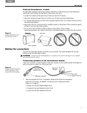
... cm) from any other surface. • Do not block the ventilation grilles located on the bottom of the module.! WARNING: Connecting the small speakers to a receiver can cause a reduction in damage to locate the source of the room as follows! (Figure 5 on the module. Impeding ventilation... English Español Français Figure 3 Position options for the three front speakers. Figure 4 Speaker cable connection to an output jack on the module and to the speaker Connecting speakers to the Acoustimass module Insert the connector on each connector to the label on each...
... cm) from any other surface. • Do not block the ventilation grilles located on the bottom of the module.! WARNING: Connecting the small speakers to a receiver can cause a reduction in damage to locate the source of the room as follows! (Figure 5 on the module. Impeding ventilation... English Español Français Figure 3 Position options for the three front speakers. Figure 4 Speaker cable connection to an output jack on the module and to the speaker Connecting speakers to the Acoustimass module Insert the connector on each connector to the label on each...
User Manual
Page 8
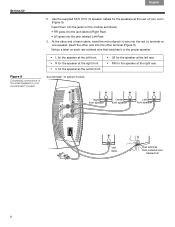
... the center front Acoustimass® 10 system module • LR for the speaker at the left rear • RR for the speakers at the right rear Right front speaker Center front speaker Left front speaker RR label Red terminal Red-collared wire labeled LR 8 At the other terminal (Figure 5). ...Use the supplied 50-ft (15.2 m) speaker cables for the speaker at the rear of each cable,...
... the center front Acoustimass® 10 system module • LR for the speaker at the left rear • RR for the speakers at the right rear Right front speaker Center front speaker Left front speaker RR label Red terminal Red-collared wire labeled LR 8 At the other terminal (Figure 5). ...Use the supplied 50-ft (15.2 m) speaker cables for the speaker at the rear of each cable,...

User Manual
Page 9
... + and - to -). • Attach each red-collared wire (+) to the appropriate + terminal. • Attach each other end of the connections (+ to the appropriate - Unlike the speaker cables, this could damage your surround receiver. Acoustimass module. The single RCA connector at that inserts into the Audio Input jack on your receiver to...
... + and - to -). • Attach each red-collared wire (+) to the appropriate + terminal. • Attach each other end of the connections (+ to the appropriate - Unlike the speaker cables, this could damage your surround receiver. Acoustimass module. The single RCA connector at that inserts into the Audio Input jack on your receiver to...
User Manual
Page 10
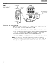
... Before plugging in the Acoustimass module, check all connections from the receiver to the the module and the module to the small speakers (Figure 8). • Make sure all cube speaker arrays are connected to the proper terminals according to their position in your room. • Check to be sure all wires are... all the connections check out, plug the power cord from the Acoustimass module into an AC (mains) outlet. to - Plug in the receiver also. Note: Bose recommends using a quality surge suppressor on .
... Before plugging in the Acoustimass module, check all connections from the receiver to the the module and the module to the small speakers (Figure 8). • Make sure all cube speaker arrays are connected to the proper terminals according to their position in your room. • Check to be sure all wires are... all the connections check out, plug the power cord from the Acoustimass module into an AC (mains) outlet. to - Plug in the receiver also. Note: Bose recommends using a quality surge suppressor on .
User Manual
Page 11
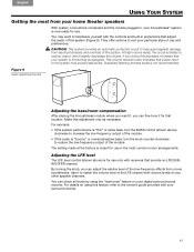
the audio of the module. • If the audio is meant for use in the most from your home theater speakers With system connections completed and the module plugged in protections that adjust ! If you notice this adjustment only as designed. Sustained listening at ... necessary. location. By turning the knob, you can fine-tune it to increase the low-frequency output of this feature, refer to suit your other speaker channels. preferences. For example: • If the system performance is "thin" or lacks bass, turn the knob counter-clockwise ! You can adjust the ...
the audio of the module. • If the audio is meant for use in the most from your home theater speakers With system connections completed and the module plugged in protections that adjust ! If you notice this adjustment only as designed. Sustained listening at ... necessary. location. By turning the knob, you can fine-tune it to increase the low-frequency output of this feature, refer to suit your other speaker channels. preferences. For example: • If the system performance is "thin" or lacks bass, turn the knob counter-clockwise ! You can adjust the ...
User Manual
Page 12
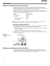
... your receiver. For additional setup and operating information, please refer to the owner's guide provided with the audio output of your DVD player. Speaker • Left and right • Center • Left and right surround • LFE/Subwoofer Receiver setting LARGE LARGE LARGE ON Figure ...recommend that came with your surround receiver. Français Español English USING YOUR SYSTEM Setting your digital surround sound receiver Speakers in the setup menu of digital surround receivers. To make changes, use the digital display menu on how to change this setting...
... your receiver. For additional setup and operating information, please refer to the owner's guide provided with the audio output of your DVD player. Speaker • Left and right • Center • Left and right surround • LFE/Subwoofer Receiver setting LARGE LARGE LARGE ON Figure ...recommend that came with your surround receiver. Français Español English USING YOUR SYSTEM Setting your digital surround sound receiver Speakers in the setup menu of digital surround receivers. To make changes, use the digital display menu on how to change this setting...
User Manual
Page 13
For example, select DVD audio on your Bose® dealer to arrange for service. No bass • Be sure the speaker connections from the receiver to the amplifier are plugged into an operating at the receiver. to the receiver. 13 No sound • Increase ...the volume. • Disconnect any headphones. • Check the speaker connections. • Make sure that the receiver is correct. Problem What to do System does not function • Make sure the receiver and powered ...
For example, select DVD audio on your Bose® dealer to arrange for service. No bass • Be sure the speaker connections from the receiver to the amplifier are plugged into an operating at the receiver. to the receiver. 13 No sound • Increase ...the volume. • Disconnect any headphones. • Check the speaker connections. • Make sure that the receiver is correct. Problem What to do System does not function • Make sure the receiver and powered ...
User Manual
Page 14
... list included in solving problems, contact the Bose® Customer Service office ! Limited warranty Your Acoustimass® speaker system is not taken. Details! Failure to your enjoyment of your authorized Bose dealer. Or to contact Bose directly, refer to the small speakers. Cleaning the speakers The cabinets of the Acoustimass speaker system. • UTS-20 table stands...
... list included in solving problems, contact the Bose® Customer Service office ! Limited warranty Your Acoustimass® speaker system is not taken. Details! Failure to your enjoyment of your authorized Bose dealer. Or to contact Bose directly, refer to the small speakers. Cleaning the speakers The cabinets of the Acoustimass speaker system. • UTS-20 table stands...
User Manual
Page 15
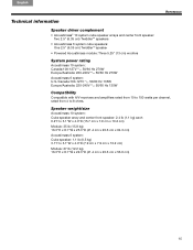
... Acoustimass 6 system:! English Español Français REFERENCE Technical information Speaker driver complement • Acoustimass® 10 system cube speaker arrays and center front speaker: ! rated from 10 to 8 ohms. Speaker weight/size Acoustimass 10 system: Cube speaker array and center front speaker: 2.4 lb (1.1 kg) each! 6.2"H x 3.1"W x 4.0"D (15.7 cm x 7.9 cm x 10.2 cm) Module: 35 lb...
... Acoustimass 6 system:! English Español Français REFERENCE Technical information Speaker driver complement • Acoustimass® 10 system cube speaker arrays and center front speaker: ! rated from 10 to 8 ohms. Speaker weight/size Acoustimass 10 system: Cube speaker array and center front speaker: 2.4 lb (1.1 kg) each! 6.2"H x 3.1"W x 4.0"D (15.7 cm x 7.9 cm x 10.2 cm) Module: 35 lb...


