
Owner's guide
Page 1
The Bose® Acoustimass® 5 Series III Speaker System Owner's Guide October 22, 2001 AM196451_05_V.pdf
The Bose® Acoustimass® 5 Series III Speaker System Owner's Guide October 22, 2001 AM196451_05_V.pdf

Owner's guide
Page 2
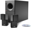
... help you with many years of the Directive, is significantly different from other speakers. Your system features new third generation Acoustimass cube speaker arrays, a product of the Bose® Acoustimass® 5 Series III speaker system. Important information Please read this owner's guide The set up and operation of your system properly and enjoy all of its advanced features. These cube speakers deliver more lifelike sound...
... help you with many years of the Directive, is significantly different from other speakers. Your system features new third generation Acoustimass cube speaker arrays, a product of the Bose® Acoustimass® 5 Series III speaker system. Important information Please read this owner's guide The set up and operation of your system properly and enjoy all of its advanced features. These cube speakers deliver more lifelike sound...

Owner's guide
Page 3
... air from the wall outlet before using this product. 2. Do not attempt to rain or moisture, does not operate normally, or has been dropped - Read these instructions - See product enclosure for your outlet, consult an electrician for a Class B digital device, pursuant to dangerous voltages or other hazards. Opening or removing covers may touch dangerous voltage points or short-out parts...
... air from the wall outlet before using this product. 2. Do not attempt to rain or moisture, does not operate normally, or has been dropped - Read these instructions - See product enclosure for your outlet, consult an electrician for a Class B digital device, pursuant to dangerous voltages or other hazards. Opening or removing covers may touch dangerous voltage points or short-out parts...

Owner's guide
Page 4
... page. Avoid power lines - Use proper power sources - Ground all outdoor antennas - Section 810 of the National Electrical Code ANSI/ NFPA No. 70 provides information with them may be sure the antenna or cable system is connected to the antenna grounding illustration on the product. 19. Antenna grounding Example of the lead-in the operating instructions or as...
... page. Avoid power lines - Use proper power sources - Ground all outdoor antennas - Section 810 of the National Electrical Code ANSI/ NFPA No. 70 provides information with them may be sure the antenna or cable system is connected to the antenna grounding illustration on the product. 19. Antenna grounding Example of the lead-in the operating instructions or as...

Owner's guide
Page 5
... Receiver/amplifier considerations 10 Maintaining Your Acoustimass 5 Series III Speaker System Maintaining your speaker system 11 Troubleshooting ...11 Product Information Technical information 12 Available Accessories 12 Warranty period ...12 Customer Service ...12 Bose® Corporation inside back cover For your records Serial numbers are located on the connection panel of the Acoustimass module. Examining the cables and connections 5 4. AM196451_05_V.pdf October 23, 2001 3 Unpacking the carton...
... Receiver/amplifier considerations 10 Maintaining Your Acoustimass 5 Series III Speaker System Maintaining your speaker system 11 Troubleshooting ...11 Product Information Technical information 12 Available Accessories 12 Warranty period ...12 Customer Service ...12 Bose® Corporation inside back cover For your records Serial numbers are located on the connection panel of the Acoustimass module. Examining the cables and connections 5 4. AM196451_05_V.pdf October 23, 2001 3 Unpacking the carton...

Owner's guide
Page 6
...; Owner's guide • Quick set up guide 4 October 23, 2001 AM196451_05_V.pdf The remaining sections provide more detailed information on your warranty card. For one, the system adjusts to deliver a lifelike musical performance formerly associated with the parts identified in the original carton and notify Bose or your authorized Bose dealer immediately. • Remove any part of this Virtually Invisible® speaker system...
...; Owner's guide • Quick set up guide 4 October 23, 2001 AM196451_05_V.pdf The remaining sections provide more detailed information on your warranty card. For one, the system adjusts to deliver a lifelike musical performance formerly associated with the parts identified in the original carton and notify Bose or your authorized Bose dealer immediately. • Remove any part of this Virtually Invisible® speaker system...

Owner's guide
Page 7
... for the left and right cube arrays. If you do so, use similar gauge or thicker wire, and make sure you choose to stand the module on its connection end, the feet must be placed near a television. AM196451_05_V.pdf October 23, 2001 5 Allow at each connection. • The cube arrays and the Acoustimass module have red positive (+) connections. Figure...
... for the left and right cube arrays. If you do so, use similar gauge or thicker wire, and make sure you choose to stand the module on its connection end, the feet must be placed near a television. AM196451_05_V.pdf October 23, 2001 5 Allow at each connection. • The cube arrays and the Acoustimass module have red positive (+) connections. Figure...

Owner's guide
Page 8
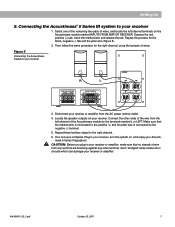
... the terminal tab on the rear of the left cube speaker From right cube speaker To receiver or amplifier 6 October 23, 2001 AM196451_05_V.pdf Connect the other pair of the Acoustimass module (Figure 4). 5. Make sure that the marked wire is connected to the positive (+) and the plain wire is connected to the Acoustimass module or damage will be connected directly to the negative (-) terminal...
... the terminal tab on the rear of the left cube speaker From right cube speaker To receiver or amplifier 6 October 23, 2001 AM196451_05_V.pdf Connect the other pair of the Acoustimass module (Figure 4). 5. Make sure that the marked wire is connected to the positive (+) and the plain wire is connected to the Acoustimass module or damage will be connected directly to the negative (-) terminal...
Owner's guide
Page 9
... or amplifier from the AC power (mains) outlet. 4. Make sure that no strands of wire from the left channel terminals on your Acoustimass 5 Series III speakers! Then follow the same procedure for the right channel, using the last pair of the wire from any terminal are brushing against any other ends of wires. English Setting Up 5. AM196451_05_V.pdf October 23, 2001 7 Select one...
... or amplifier from the AC power (mains) outlet. 4. Make sure that no strands of wire from the left channel terminals on your Acoustimass 5 Series III speakers! Then follow the same procedure for the right channel, using the last pair of the wire from any terminal are brushing against any other ends of wires. English Setting Up 5. AM196451_05_V.pdf October 23, 2001 7 Select one...

Owner's guide
Page 10
... 5 Series III speaker system, the following test will help you determine that it exhibits less, check to make sure that your components are connected as 15 feet (4.5 m). B. Now, turn the balance all the way to the left -only or right-only positions. Return the balance control to the right. You may be working properly: A. Play a musical selection with the positions of direct and...
... 5 Series III speaker system, the following test will help you determine that it exhibits less, check to make sure that your components are connected as 15 feet (4.5 m). B. Now, turn the balance all the way to the left -only or right-only positions. Return the balance control to the right. You may be working properly: A. Play a musical selection with the positions of direct and...
Owner's guide
Page 11
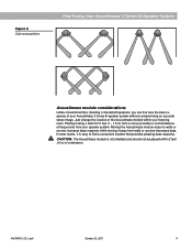
... within your Acoustimass 5 Series III speaker system without compromising an accurate stereo image. Just change the location of the Acoustimass module within 2 feet (.6 m) of a television. AM196451_05_V.pdf October 23, 2001 9 In most rooms, it along a wall 3 to find a convenient location that provides pleasing bass response. English Figure 6 Cube array positions Fine Tuning Your Acoustimass® 5 Series III Speaker System Acoustimass module...
... within your Acoustimass 5 Series III speaker system without compromising an accurate stereo image. Just change the location of the Acoustimass module within 2 feet (.6 m) of a television. AM196451_05_V.pdf October 23, 2001 9 In most rooms, it along a wall 3 to find a convenient location that provides pleasing bass response. English Figure 6 Cube array positions Fine Tuning Your Acoustimass® 5 Series III Speaker System Acoustimass module...

Owner's guide
Page 12
... types of sound-absorbing furnishings, such as throw carpets or drapes will decrease bass. Remember, though, that power input may be exceeding safe levels. For further information, refer to your receiver or amplifier. English Fine Tuning Your Acoustimass® 5 Series III Speaker System Using your speaker system to its best advantage Your speaker system requires very little attention when set up...
... types of sound-absorbing furnishings, such as throw carpets or drapes will decrease bass. Remember, though, that power input may be exceeding safe levels. For further information, refer to your receiver or amplifier. English Fine Tuning Your Acoustimass® 5 Series III Speaker System Using your speaker system to its best advantage Your speaker system requires very little attention when set up...

Owner's guide
Page 13
... Acoustimass 5 speaker system does not play or sounds distorted • Turn off the receiver or amplifier and disconnect the Acoustimass 5 speaker system. Bose will verify any problem within the terms of the warranty at minimum inconvenience to remedy any defects and arrange for help). If the fuses blow again, have the unit checked by the Bose factory. AM196451_05_V.pdf October 23...
... Acoustimass 5 speaker system does not play or sounds distorted • Turn off the receiver or amplifier and disconnect the Acoustimass 5 speaker system. Bose will verify any problem within the terms of the warranty at minimum inconvenience to remedy any defects and arrange for help). If the fuses blow again, have the unit checked by the Bose factory. AM196451_05_V.pdf October 23...

Owner's guide
Page 14
... phone numbers. 12 October 23, 2001 AM196451_05_V.pdf English Product Information Technical Information Features Direct/Reflecting® speaker design Acoustimass® speaker system Syncom® II computerized quality control Automatic system protection circuitry Driver Complement Two 5.25 inch (13.3 cm) low-frequency drivers in Acoustimass module Four 2.5 inch (6.4 cm) magnetically shielded, wide-range drivers in ordering accessories or solving problems, contact Bose Customer Service...
... phone numbers. 12 October 23, 2001 AM196451_05_V.pdf English Product Information Technical Information Features Direct/Reflecting® speaker design Acoustimass® speaker system Syncom® II computerized quality control Automatic system protection circuitry Driver Complement Two 5.25 inch (13.3 cm) low-frequency drivers in Acoustimass module Four 2.5 inch (6.4 cm) magnetically shielded, wide-range drivers in ordering accessories or solving problems, contact Bose Customer Service...

Owner's guide
Page 15
... TEL 31-878850 FAX 31-274891 United Kingdom Bose Limited 1 Ambley Green Gillingham Business Park Gillingham, Kent ME8 0NJ TEL 0870-741-4500 FAX 0870-741-4545 From other locations Bose Customer Service, 1 New York Ave. USA Bose Corporation, The Mountain Framingham, MA 01701-9168 1-800-367-4008 Phone hours - ET (eastern time): Weekdays 8:30 a.m. to...
... TEL 31-878850 FAX 31-274891 United Kingdom Bose Limited 1 Ambley Green Gillingham Business Park Gillingham, Kent ME8 0NJ TEL 0870-741-4500 FAX 0870-741-4545 From other locations Bose Customer Service, 1 New York Ave. USA Bose Corporation, The Mountain Framingham, MA 01701-9168 1-800-367-4008 Phone hours - ET (eastern time): Weekdays 8:30 a.m. to...

Owner's guide
Page 16
Warranty © 1999 Bose Corporation, The Mountain, Framingham, MA 01701-9168 USA 196451 AM Rev. 05 JN00049
Warranty © 1999 Bose Corporation, The Mountain, Framingham, MA 01701-9168 USA 196451 AM Rev. 05 JN00049


