
Use & Care Manual
Page 3
... or oven bottom. Safety Important Safety Instructions READ AND SAVE THESE INSTRUCTIONS Important Safety Instructions Fire Safety • Do not use . Before using your Warranty. Installation of these liners may ignite. • WARNING - About This Manual How This Manual Is Organized This manual contains several sections: • The Overview section describes...
... or oven bottom. Safety Important Safety Instructions READ AND SAVE THESE INSTRUCTIONS Important Safety Instructions Fire Safety • Do not use . Before using your Warranty. Installation of these liners may ignite. • WARNING - About This Manual How This Manual Is Organized This manual contains several sections: • The Overview section describes...
Use & Care Manual
Page 6
...result in injury. • Do not operate this appliance if it for , your new appliance has been designed to be properly installed and grounded by a qualified technician. Proper relationship of corrosive chemicals in heating or cleaning will also improve efficiency. • Cookware not... will damage the appliance and could result. Cleaning solutions and spillovers may not be followed, including those in or near this manual. Proper Installation and Maintenance • • • • WARNING: When properly cared for easy reference. Read all servicing to persons. These ...
...result in injury. • Do not operate this appliance if it for , your new appliance has been designed to be properly installed and grounded by a qualified technician. Proper relationship of corrosive chemicals in heating or cleaning will also improve efficiency. • Cookware not... will damage the appliance and could result. Cleaning solutions and spillovers may not be followed, including those in or near this manual. Proper Installation and Maintenance • • • • WARNING: When properly cared for easy reference. Read all servicing to persons. These ...

Use & Care Manual
Page 9
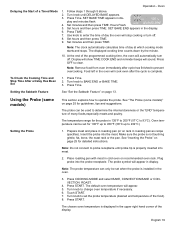
Tilt rack up and pull the rest of the way out. Bring rack to allow stop is not installed correctly. The Full Extension Rack allows for easier access to the user. Grasp the bottom section and pull straight out. 2. If the top rack will ...
Tilt rack up and pull the rest of the way out. Bring rack to allow stop is not installed correctly. The Full Extension Rack allows for easier access to the user. Grasp the bottom section and pull straight out. 2. If the top rack will ...

Use & Care Manual
Page 10
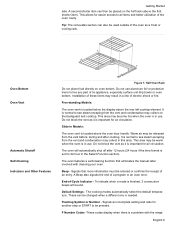
... side toward the back of the rack until it passes the stop (ball). 3. With the right half of the rack removed, you until it is installed correctly after reassembly. Place rack on the bottom rack. Dry thoroughly. Closed Position Back of Rack Stop (Ball) Front of Rack Reassembly Figure 5: Disassembly CAUTION...
... side toward the back of the rack until it passes the stop (ball). 3. With the right half of the rack removed, you until it is installed correctly after reassembly. Place rack on the bottom rack. Dry thoroughly. Closed Position Back of Rack Stop (Ball) Front of Rack Reassembly Figure 5: Disassembly CAUTION...
Use & Care Manual
Page 11
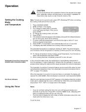
... . Do not block the vent as a trivet or cooling rack. To indicate when a mode is in Models: The oven vent is important for air circulation. Installation of these liners may be released from the vent and condensation may be warm when the oven is finished, 3 consecutive beeps will automatically shut off...
... . Do not block the vent as a trivet or cooling rack. To indicate when a mode is in Models: The oven vent is important for air circulation. Installation of these liners may be released from the vent and condensation may be warm when the oven is finished, 3 consecutive beeps will automatically shut off...
Use & Care Manual
Page 13
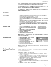
... do not complete the operation of setting the clock, the oven will be a slight delay before each message (or feature) can set the clock after installation or after a power failure. Press START to desired setting and press START. Turn knob to select CLOCK. 3. Turn knob to select hour and AM or...
... do not complete the operation of setting the clock, the oven will be a slight delay before each message (or feature) can set the clock after installation or after a power failure. Press START to desired setting and press START. Turn knob to select CLOCK. 3. Turn knob to select hour and AM or...
Use & Care Manual
Page 19
... oven bottom. Press COOKING MODE. 2. The actual temperature increases until set the timer: English 17 When the Automatic Convection Conversion feature is turned off oven. Installation of electric shock or fire. To change temperature during cooking, press Temperature. Press START. 6. If this occurs, press START. 6: 35 PM 380 100 BAKE 4. When...
... oven bottom. Press COOKING MODE. 2. The actual temperature increases until set the timer: English 17 When the Automatic Convection Conversion feature is turned off oven. Installation of electric shock or fire. To change temperature during cooking, press Temperature. Press START. 6. If this occurs, press START. 6: 35 PM 380 100 BAKE 4. When...
Use & Care Manual
Page 21
... end of the display. Display will show TIME COOK END and reminder beeps will appear. 5. Note: Remove food from oven immediately after the cycle is installed in the upper right hand corner of the programmed cooking time, the oven will cook even after cycle has finished to 93°C). To Check...
... end of the display. Display will show TIME COOK END and reminder beeps will appear. 5. Note: Remove food from oven immediately after the cycle is installed in the upper right hand corner of the programmed cooking time, the oven will cook even after cycle has finished to 93°C). To Check...
Use & Care Manual
Page 22
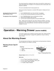
... English 20 It starts at serving temperature. Turn the knob to operate the warming drawer. The oven temperature will not self-clean with the probe installed in 5°F increments until the probe is complete. Press start and PROBE TEMP will remain in oven during self-clean. Note: Always remove probe from...
... English 20 It starts at serving temperature. Turn the knob to operate the warming drawer. The oven temperature will not self-clean with the probe installed in 5°F increments until the probe is complete. Press start and PROBE TEMP will remain in oven during self-clean. Note: Always remove probe from...
Use & Care Manual
Page 41
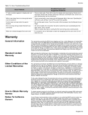
... and customary manner (commercial use convection Warm air or steam escapes from whom you may have been defective under conditions of Installation. Slide-in materials and workmanship for the bake mode. BSH shall not reimburse any Range that don't use of the...The warranties provided in this warranty shall be deemed normal or customary), (2) misuse, abuse, accidents or neglect, (3) improper operation, maintenance, installation or unauthorized service, (4) adjustment or alteration or modification of the Range in this warranty sets out your finger. As used in other circumstances...
... and customary manner (commercial use convection Warm air or steam escapes from whom you may have been defective under conditions of Installation. Slide-in materials and workmanship for the bake mode. BSH shall not reimburse any Range that don't use of the...The warranties provided in this warranty shall be deemed normal or customary), (2) misuse, abuse, accidents or neglect, (3) improper operation, maintenance, installation or unauthorized service, (4) adjustment or alteration or modification of the Range in this warranty sets out your finger. As used in other circumstances...
Installation Instructions
Page 2
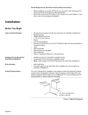
... You Begin 2 Tools and Parts Needed 2 Additional Parts Needed for Hard Wire Installations 2 Parts Included 2 Cabinet Requirements 2 Electrical Requirements 4 Installation 5 Installation Tips 5 Install Ventilation 5 Prepare Walls and Floor 5 Prepare Range 5 Install Strain Relief 5 Connect Electric 6 Attach Anti-Tip Bracket to hearing from you! Huntington Beach, CA 92649 We look forward to Floor 12 Complete the...
... You Begin 2 Tools and Parts Needed 2 Additional Parts Needed for Hard Wire Installations 2 Parts Included 2 Cabinet Requirements 2 Electrical Requirements 4 Installation 5 Installation Tips 5 Install Ventilation 5 Prepare Walls and Floor 5 Prepare Range 5 Install Strain Relief 5 Connect Electric 6 Attach Anti-Tip Bracket to hearing from you! Huntington Beach, CA 92649 We look forward to Floor 12 Complete the...
Installation Instructions
Page 3
...not followed exactly, a fire or explosion may result causing property damage, personal injury or death. • Ask your appliance is properly installed and grounded by a qualified technician in accordance with the National Electrical Code ANSI/ NFPA No. 7 latest edition and local electrical code ...seriously injured. • To eliminate the risk of the appliance unless specifically recommended in the literature package for easier handling and installation. Safety Codes and Specifications • Be sure your dealer to reach items could be reduced by removing leveling legs, panels, ...
...not followed exactly, a fire or explosion may result causing property damage, personal injury or death. • Ask your appliance is properly installed and grounded by a qualified technician in accordance with the National Electrical Code ANSI/ NFPA No. 7 latest edition and local electrical code ...seriously injured. • To eliminate the risk of the appliance unless specifically recommended in the literature package for easier handling and installation. Safety Codes and Specifications • Be sure your dealer to reach items could be reduced by removing leveling legs, panels, ...
Installation Instructions
Page 4
...; Note: Power Supply Cord Kit Not Necessary For Hard Wire Installations • Anti-Tip Bracket • Terminal Lugs (For Use With Hard Wire Installations) (not necessary for Canadian installations) This unit is to be installed (0.47" (12 mm) clearance from being turned ON accidentally.... at the service panel. Allow a minimum of combustible materials. to cabinet required in case of an emergency.Installation • 50 Amp Power Supply Cord Kit (not necessary for Canadian installations) • Measuring Tape • Phillips Head Screwdriver • 1-1/4" (31.8 mm) Wrench • Pencil...
...; Note: Power Supply Cord Kit Not Necessary For Hard Wire Installations • Anti-Tip Bracket • Terminal Lugs (For Use With Hard Wire Installations) (not necessary for Canadian installations) This unit is to be installed (0.47" (12 mm) clearance from being turned ON accidentally.... at the service panel. Allow a minimum of combustible materials. to cabinet required in case of an emergency.Installation • 50 Amp Power Supply Cord Kit (not necessary for Canadian installations) • Measuring Tape • Phillips Head Screwdriver • 1-1/4" (31.8 mm) Wrench • Pencil...
Installation Instructions
Page 6
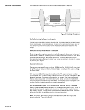
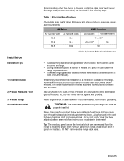
...switch and fuses either 120/240 VAC or 120/208 VAC. Most wiring codes require a separate circuit with the range cord already installed. Refer to be installed on either in the main entrance panel or in order to determine the required amperage. Note: In Canada, the range is ...must be increased to Step 9. In compliance with the NEC, a separate circuit is adequate. Always choose a range power cord set must be installed with Ranges." Verify that the present electric service to your local utility company to house is adequate. If using the aluminum terminal lugs included ...
...switch and fuses either 120/240 VAC or 120/208 VAC. Most wiring codes require a separate circuit with the range cord already installed. Refer to be installed on either in the main entrance panel or in order to determine the required amperage. Note: In Canada, the range is ...must be increased to Step 9. In compliance with the NEC, a separate circuit is adequate. Always choose a range power cord set must be installed with Ranges." Verify that the present electric service to your local utility company to house is adequate. If using the aluminum terminal lugs included ...
Installation Instructions
Page 7
... reattach. Place range in table to determine amperage requirements. Reference kW rating in front of cabinets where it from opening while installing the range. • During installation, place a portion of the box or a piece of cloth under the range to protect floors. • To make... 50 * Varies by location. For most kitchens a certified hood rating of a ventilation hood above this range. The range hood must be installed. Feed range cord through hole and strain relief up to instructions furnished with the hood. Remove any obstructions (extra electrical or gas connections, ...
... reattach. Place range in table to determine amperage requirements. Reference kW rating in front of cabinets where it from opening while installing the range. • During installation, place a portion of the box or a piece of cloth under the range to protect floors. • To make... 50 * Varies by location. For most kitchens a certified hood rating of a ventilation hood above this range. The range hood must be installed. Feed range cord through hole and strain relief up to instructions furnished with the hood. Remove any obstructions (extra electrical or gas connections, ...
Installation Instructions
Page 8
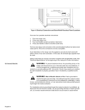
... neutral conductor is properly grounded, have it checked by a qualified electrician. Four wire flexible conduit connection (hard wire) 4. In this manual for new branch-circuit installations (1996 NEC), mobile homes, and recreational vehicles, or in knockout panel here. WARNING: To prevent electrical shock, the grounding prong on the range cord should... where local codes permit, three wire connections are four possible electrical connections: 1. WARNING: Risk of this case, the terminal lugs supplied must be used. For installations where grounding through a ground strap.
... neutral conductor is properly grounded, have it checked by a qualified electrician. Four wire flexible conduit connection (hard wire) 4. In this manual for new branch-circuit installations (1996 NEC), mobile homes, and recreational vehicles, or in knockout panel here. WARNING: To prevent electrical shock, the grounding prong on the range cord should... where local codes permit, three wire connections are four possible electrical connections: 1. WARNING: Risk of this case, the terminal lugs supplied must be used. For installations where grounding through a ground strap.
Installation Instructions
Page 9
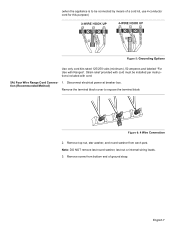
Strain relief provided with cord must be connected by means of ground strap. English 7 tion (Recommended Method) Remove the terminal block cover to be installed per instructions included with Ranges". Remove screw from each post. Disconnect electrical power at breaker box. Note: DO NOT remove last round washer, last nut ...
Strain relief provided with cord must be connected by means of ground strap. English 7 tion (Recommended Method) Remove the terminal block cover to be installed per instructions included with Ranges". Remove screw from each post. Disconnect electrical power at breaker box. Note: DO NOT remove last round washer, last nut ...

Installation Instructions
Page 14
... each clamping screw with the appropriate torque (See table below). 6. lug clamping screw wire Figure 17: Attaching Wire to the wall, floor or cabinet by installing the Anti-Tip Device supplied. Properly secure flexible conduit at this time.
... each clamping screw with the appropriate torque (See table below). 6. lug clamping screw wire Figure 17: Attaching Wire to the wall, floor or cabinet by installing the Anti-Tip Device supplied. Properly secure flexible conduit at this time.

Installation Instructions
Page 15
... by rotating the adjustable leg supports on electrical power. rear wall cabinet wall 1 9/16" (39.7 mm) from back wall when properly installed. 3. for wood floor use wood screws for cleaning, service, or any other reason, ensure that the left back leg slides under the ...range itself. 1. Move range close enough to the opening to center of screw hole floor flush against the wall. drawer 7) Complete the installation wrench adjustable leg Figure 19: Adjusting the Leg Support 2. Check range for mounting surface, not included. (i.e.; Personal injury might result from spilled...
... by rotating the adjustable leg supports on electrical power. rear wall cabinet wall 1 9/16" (39.7 mm) from back wall when properly installed. 3. for wood floor use wood screws for cleaning, service, or any other reason, ensure that the left back leg slides under the ...range itself. 1. Move range close enough to the opening to center of screw hole floor flush against the wall. drawer 7) Complete the installation wrench adjustable leg Figure 19: Adjusting the Leg Support 2. Check range for mounting surface, not included. (i.e.; Personal injury might result from spilled...

