
Installation Instructions
Page 3
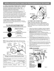
... 10 Fig. 12 3 The Rear Access Cover must have either 7/8" dia. Refer to Fig.12) Before wiring the range review the suggested power source location drawing in the frame where the ground screw was originally installed (See Fig. 12). 5. MODELS... all screws are loosened or removed. 3. INSTALLATION INSTRUCTIONS FOR FREESTANDING ELECTRIC RANGE 2b. Electrical failure or loss of wires must disconnect the ground strap. Wire electrical wall Receptacle types & recommended mounting orientation on end of electrical connection may be accessible. 3 & 4 - POWER CORD CONNECTIONS ...
... 10 Fig. 12 3 The Rear Access Cover must have either 7/8" dia. Refer to Fig.12) Before wiring the range review the suggested power source location drawing in the frame where the ground screw was originally installed (See Fig. 12). 5. MODELS... all screws are loosened or removed. 3. INSTALLATION INSTRUCTIONS FOR FREESTANDING ELECTRIC RANGE 2b. Electrical failure or loss of wires must disconnect the ground strap. Wire electrical wall Receptacle types & recommended mounting orientation on end of electrical connection may be accessible. 3 & 4 - POWER CORD CONNECTIONS ...
Installation Instructions
Page 4
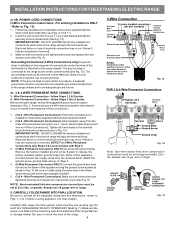
... & plate as shown in ./lbs. Wire Permanent Connection - follow Steps 1,2 & 5 below . Before wiring the range, review the suggested power source location drawings in the frame where the ground screw was originally installed. 5. (3 & 4 - Electrical failure or loss of the range. 4 Fig. 13 Fig. 14 Note: Non-terminated field wire compression connections must be set at...
... & plate as shown in ./lbs. Wire Permanent Connection - follow Steps 1,2 & 5 below . Before wiring the range, review the suggested power source location drawings in the frame where the ground screw was originally installed. 5. (3 & 4 - Electrical failure or loss of the range. 4 Fig. 13 Fig. 14 Note: Non-terminated field wire compression connections must be set at...