Installation Instructions
Page 3
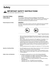
...Install anti-tip device packaged with one or more of the following Standards: • UL 858, The Standard for the Safety of Household Electric Ranges • UL 923, The Standard for the Safety of Microwave Cooking Appliances • UL 507, The Standard for the Safety of Electric Fans... • ANSI Z21.1, The American National Standard for Household Cooking Gas Appliances • CAN/CSA-C22.2 No. 113-M1984 Fans and Ventilators • CAN/CSA-C22.2 No. 61-M89 Household Cooking Ranges English 1 WARNING: All ranges can cause injury or property damage. If cabinet storage is heavy and...
...Install anti-tip device packaged with one or more of the following Standards: • UL 858, The Standard for the Safety of Household Electric Ranges • UL 923, The Standard for the Safety of Microwave Cooking Appliances • UL 507, The Standard for the Safety of Electric Fans... • ANSI Z21.1, The American National Standard for Household Cooking Gas Appliances • CAN/CSA-C22.2 No. 113-M1984 Fans and Ventilators • CAN/CSA-C22.2 No. 61-M89 Household Cooking Ranges English 1 WARNING: All ranges can cause injury or property damage. If cabinet storage is heavy and...
Installation Instructions
Page 4
...comply with a cord and plug, do not cut or remove the ground prong. Save these instructions for the local electrical inspector's use with ranges" shall be used. • Installer - English 2 If there is any doubt as to whether the wall receptacle is properly installed and grounded... required by the National Electrical Code (or Canadian Electrical Code), this appliance must be installed on the data plate. Safety Electric Safety Gas Safety It is the responsibility of the owner and the installer to determine if additional requirements and/or standards apply to specific installations. ...
...comply with a cord and plug, do not cut or remove the ground prong. Save these instructions for the local electrical inspector's use with ranges" shall be used. • Installer - English 2 If there is any doubt as to whether the wall receptacle is properly installed and grounded... required by the National Electrical Code (or Canadian Electrical Code), this appliance must be installed on the data plate. Safety Electric Safety Gas Safety It is the responsibility of the owner and the installer to determine if additional requirements and/or standards apply to specific installations. ...
Installation Instructions
Page 6
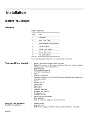
...Phillips Head Screwdriver • 1-1/4" (31.8 mm) Wrench • Pencil • T-20 Torx Screwdriver • Screws (2) and Anchors (2) for Gas Leaks 7. Connect Electric 5. Connect Gas Supply 6. Test for Anti-Tip Bracket (Style will vary depending on mounting surface) • Level • Drill and Drill Bit • Soapy ...Table 1: Overview Step Task 1. Preparation 2. Tools and Parts Needed Additional Parts Needed For Hard Wire Installations • Range Power Supply Cord Kit (240V -30 Amp) Note: Not necessary for step-by-step instructions. Apply Foam Tape 3.
...Phillips Head Screwdriver • 1-1/4" (31.8 mm) Wrench • Pencil • T-20 Torx Screwdriver • Screws (2) and Anchors (2) for Gas Leaks 7. Connect Electric 5. Connect Gas Supply 6. Test for Anti-Tip Bracket (Style will vary depending on mounting surface) • Level • Drill and Drill Bit • Soapy ...Table 1: Overview Step Task 1. Preparation 2. Tools and Parts Needed Additional Parts Needed For Hard Wire Installations • Range Power Supply Cord Kit (240V -30 Amp) Note: Not necessary for step-by-step instructions. Apply Foam Tape 3.
Installation Instructions
Page 9
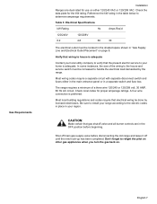
... be located in the shaded space shown in "Gas Supply Line and Electrical Outlet Placement" on . Verify that wiring to house is adequate Contact your region. The range requires a minimum of the wiring to your range according to determine amperage requirements. English 7 Shut ...Req'd 120/240V 6.2 120/208V 4.8 60 30 The electrical outlet must be done by the range. Gas Requirements Installation Ranges are in the OFF position before disconnecting the old range and leave it off main gas supply valve before beginning. Check the data plate for proper amperage ratings.
... be located in the shaded space shown in "Gas Supply Line and Electrical Outlet Placement" on . Verify that wiring to house is adequate Contact your region. The range requires a minimum of the wiring to your range according to determine amperage requirements. English 7 Shut ...Req'd 120/240V 6.2 120/208V 4.8 60 30 The electrical outlet must be done by the range. Gas Requirements Installation Ranges are in the OFF position before disconnecting the old range and leave it off main gas supply valve before beginning. Check the data plate for proper amperage ratings.

Installation Instructions
Page 10
...surfaces constructed of 30 inches between cabinets where range is designed for use with natural gas. Prepare the countertop and cabinets as shown in Figure 5: Cutout Requirements - For use with propane (LP) gas, your range must be located in the shaded space as... shown in Figure 4: Gas Supply Line and Electrical Outlet Placement. 7 1/2" (190.5 mm) 3 1/2" 88.9 mm 4 1/2" 114.3 mm 4" (101.6 mm) 13 1/8 " (333 mm) 3...
...surfaces constructed of 30 inches between cabinets where range is designed for use with natural gas. Prepare the countertop and cabinets as shown in Figure 5: Cutout Requirements - For use with propane (LP) gas, your range must be located in the shaded space as... shown in Figure 4: Gas Supply Line and Electrical Outlet Placement. 7 1/2" (190.5 mm) 3 1/2" 88.9 mm 4 1/2" 114.3 mm 4" (101.6 mm) 13 1/8 " (333 mm) 3...

Installation Instructions
Page 12
...by safety standards, particularly self-cleaning ovens; Measure to locate bracket position as shown in the walls or floor. Clearance from range top to adjacent vertical walls must be installed according to instructions furnished with 2 screws adequate for mounting surface (i.e., for wood ... Requirements Mounting Requirements From cooktop to materials above this appliance. From range walls to adjacent vertical combustible walls on rear, right or left. Seal any obstructions (extra electrical or gas connections, etc.) so that range will rest against cabinet wall 1 9/16" (39.7 mm) ...
...by safety standards, particularly self-cleaning ovens; Measure to locate bracket position as shown in the walls or floor. Clearance from range top to adjacent vertical walls must be installed according to instructions furnished with 2 screws adequate for mounting surface (i.e., for wood ... Requirements Mounting Requirements From cooktop to materials above this appliance. From range walls to adjacent vertical combustible walls on rear, right or left. Seal any obstructions (extra electrical or gas connections, etc.) so that range will rest against cabinet wall 1 9/16" (39.7 mm) ...
Installation Instructions
Page 14
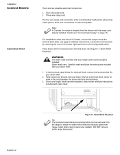
... install the strain relief: Remove knockout panel from the factory with the range cord already installed. Feed range cord through hole and strain relief up to "Connect Gas Supply" on page 16. Four wire range cord 2. Strain reliefs vary. In the knockout panel below the terminal block, remove the knockout that fits your strain...
... install the strain relief: Remove knockout panel from the factory with the range cord already installed. Feed range cord through hole and strain relief up to "Connect Gas Supply" on page 16. Four wire range cord 2. Strain reliefs vary. In the knockout panel below the terminal block, remove the knockout that fits your strain...
Installation Instructions
Page 18
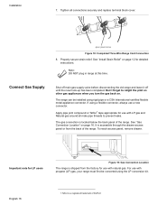
...use with propane (LP) gas, your range must first be installed using a flexible connector, always use with natural gas. Installation 7. green ground screw Figure 18: Completed Three Wire Range Cord Connection 8. Connect Gas Supply Shut off main gas supply valve before disconnecting the old range and leave it off until...shipped from the back of DuPont The gas connection is a registered trademark of the range. Note: DO NOT plug in range at this time. Tighten all male pipe threads to relight the pilot on other gas appliances when you turn the gas back on page 16. To reach...
...use with propane (LP) gas, your range must first be installed using a flexible connector, always use with natural gas. Installation 7. green ground screw Figure 18: Completed Three Wire Range Cord Connection 8. Connect Gas Supply Shut off main gas supply valve before disconnecting the old range and leave it off until...shipped from the back of DuPont The gas connection is a registered trademark of the range. Note: DO NOT plug in range at this time. Tighten all male pipe threads to relight the pilot on other gas appliances when you turn the gas back on page 16. To reach...
Installation Instructions
Page 19
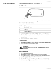
... the internal thread of the manual shutoff valve. 3. English 17 Install male 1/2" flare adaptor at gas inlet valve. Connect flexible connector at the 1/2" NPT internal thread of the range inlet. Measure back left corner of opening . 2. Install male 1/2" or 3/4" flare union adapter on... page 19. Plug in right back corner. 5. Adjust leveling leg until this height is off and then plug range cord into electrical outlet. 2. Flexible Connector Method If using rigid pipe, skip to bottom of cooktop trim. Attach Connector Installation B C A Table...
... the internal thread of the manual shutoff valve. 3. English 17 Install male 1/2" flare adaptor at gas inlet valve. Connect flexible connector at the 1/2" NPT internal thread of the range inlet. Measure back left corner of opening . 2. Install male 1/2" or 3/4" flare union adapter on... page 19. Plug in right back corner. 5. Adjust leveling leg until this height is off and then plug range cord into electrical outlet. 2. Flexible Connector Method If using rigid pipe, skip to bottom of cooktop trim. Attach Connector Installation B C A Table...

Installation Instructions
Page 21
.... English 19 Attach Rigid Pipe E D D B C B B A Gas Flow to ensure that both front legs are resting solidly on page 17. Rigid Pipe Method Adjust Front of the gas pipe stub. Carefully tip range forward to Range F Table 5: Rigid Pipe Method Letter A B C D Item Elbow;... Connect to regulator here Pipe Nipple Union Elbow E Gas Shut Off Valve F 1/2" to "Flexible Connector Method" on the...
.... English 19 Attach Rigid Pipe E D D B C B B A Gas Flow to ensure that both front legs are resting solidly on page 17. Rigid Pipe Method Adjust Front of the gas pipe stub. Carefully tip range forward to Range F Table 5: Rigid Pipe Method Letter A B C D Item Elbow;... Connect to regulator here Pipe Nipple Union Elbow E Gas Shut Off Valve F 1/2" to "Flexible Connector Method" on the...

Installation Instructions
Page 23
... trim rests against the countertop all joints and fittings between the shutoff valve and the range. Carefully tip range forward to the next step until all detection fluid residue. Complete Gas Connection 1. Access the connection through the access panel behind the drawer. Inspect for Proper...section. Note: Be careful not to apply pressure to verify that the weight of Range for leaks. Retest for Gas Leaks Installation to warming drawer element during installation. 3. Push range back into position ensuring that the left leg is under the anti-tip bracket. vents...
... trim rests against the countertop all joints and fittings between the shutoff valve and the range. Carefully tip range forward to the next step until all detection fluid residue. Complete Gas Connection 1. Access the connection through the access panel behind the drawer. Inspect for Proper...section. Note: Be careful not to apply pressure to verify that the weight of Range for leaks. Retest for Gas Leaks Installation to warming drawer element during installation. 3. Push range back into position ensuring that the left leg is under the anti-tip bracket. vents...


