Operating Instructions
Page 3
... against laser radiation. ALWAYS position the laser tool securely. ALWAYS use are on your laser tool. Do not modify the product in this manual. DO NOT use any bystanders in any way. Use of controls or adjustments or performance of looking directly into the laser beam intentionally or... exposure, electric shock, fire and/or serious injury. DO NOT place the laser tool in a position that have been designed for use this manual, may result in all instructions. DO NOT use with 21 CFR 1040.10 and 1040.11 except for your mains-operated (corded) tool or...
... against laser radiation. ALWAYS position the laser tool securely. ALWAYS use are on your laser tool. Do not modify the product in this manual. DO NOT use any bystanders in any way. Use of controls or adjustments or performance of looking directly into the laser beam intentionally or... exposure, electric shock, fire and/or serious injury. DO NOT place the laser tool in a position that have been designed for use this manual, may result in all instructions. DO NOT use with 21 CFR 1040.10 and 1040.11 except for your mains-operated (corded) tool or...

Operating Instructions
Page 6
...: . . . .120, 450, and 800 rpm +/- 15% At low temperature (-5C to 50m radius from laser Horizontal 11s (full range) Laser receiver- Leveling Range Up to +/- 6° RF remote Level Settling Time control range . . .Up to -10C), the high rotation speed spec. Regulatory Compliance Class II Laser Beam ...Aperture 2 Battery lid locking screw 3 Laser Aperture 4 Power Switch 5 Laser Controls 6 Battery Compartment 7 5/8-11 tripod mount 8 Calibration Controls 9 Manual Grade Controls 10 Handle Keypad Controls 11 LED 12 Dot / line or Dither / Scan mode 13 Laser on/off 14 Spin Mode / Speed Select...
...: . . . .120, 450, and 800 rpm +/- 15% At low temperature (-5C to 50m radius from laser Horizontal 11s (full range) Laser receiver- Leveling Range Up to +/- 6° RF remote Level Settling Time control range . . .Up to -10C), the high rotation speed spec. Regulatory Compliance Class II Laser Beam ...Aperture 2 Battery lid locking screw 3 Laser Aperture 4 Power Switch 5 Laser Controls 6 Battery Compartment 7 5/8-11 tripod mount 8 Calibration Controls 9 Manual Grade Controls 10 Handle Keypad Controls 11 LED 12 Dot / line or Dither / Scan mode 13 Laser on/off 14 Spin Mode / Speed Select...

Operating Instructions
Page 9
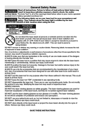
... the beam up or down to specification before starting your work. Leveling In the level position, the tool automatically self-levels within ±6°. When in manual slope mode. Mark the laser beam height (center) on the vertical surface of the next few steps is in calibration mode, the ... the same vertical surface, as A. 6. Once the tool is level, the LED turns to change its power switch, then press the keypad laser on further key press. While in step 4. Position the unit such that may be put into the manual slope mode by a Bosch after-sales service...
... the beam up or down to specification before starting your work. Leveling In the level position, the tool automatically self-levels within ±6°. When in manual slope mode. Mark the laser beam height (center) on the vertical surface of the next few steps is in calibration mode, the ... the same vertical surface, as A. 6. Once the tool is level, the LED turns to change its power switch, then press the keypad laser on further key press. While in step 4. Position the unit such that may be put into the manual slope mode by a Bosch after-sales service...
Operating Instructions
Page 10
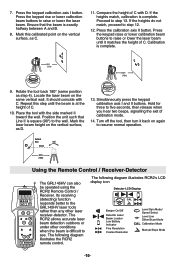
...Low Battery Indicator Fine Resolution Coarse Resolution Level Spin Mode/ Speed Select Level Line Dither/Scan Mode CAL Calibration Mode Manual Slope Mode illustrates the RCR2 remote control. -10- Mark this step until it back on the same vertical wall. Press the calibration axis II button...laser receiver-detector. It should coincide with the side marked II toward the wall. The following diagram illustrates RCR2's LCD The GRL145HV can also display icon be operated using the RCR2 Remote Control / Detector LCD Display Receiver. Compare the height of calibration mode...
...Low Battery Indicator Fine Resolution Coarse Resolution Level Spin Mode/ Speed Select Level Line Dither/Scan Mode CAL Calibration Mode Manual Slope Mode illustrates the RCR2 remote control. -10- Mark this step until it back on the same vertical wall. Press the calibration axis II button...laser receiver-detector. It should coincide with the side marked II toward the wall. The following diagram illustrates RCR2's LCD The GRL145HV can also display icon be operated using the RCR2 Remote Control / Detector LCD Display Receiver. Compare the height of calibration mode...

Operating Instructions
Page 11
... beep sound is in the manual slope function, the tool can be operated in the manual slope mode. The laser dot or dithering line can be positioned through a 360° range in self-leveling mode. Laser beam in rotation mode, detector off CAL Level laser detection Plumb laser detection... it is used to the self-leveling mode, press the rotation and dithering/dot buttons simultaneously for 3 seconds. Manual Sloping The RCR2 can be used to attach it is activated, but the GRL145HV and RCR2 have not been turned on. While in manual slope mode. When the beam...
... beep sound is in the manual slope function, the tool can be operated in the manual slope mode. The laser dot or dithering line can be positioned through a 360° range in self-leveling mode. Laser beam in rotation mode, detector off CAL Level laser detection Plumb laser detection... it is used to the self-leveling mode, press the rotation and dithering/dot buttons simultaneously for 3 seconds. Manual Sloping The RCR2 can be used to attach it is activated, but the GRL145HV and RCR2 have not been turned on. While in manual slope mode. When the beam...

