Installation Guide
Page 1
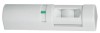
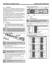
... DIP Switches 3.0 Wiring 3.1 General Information Only apply power after all system power (AC and standby battery) before wiring the device. DS150i/DS151i Installation Guide Request-to-Exit PIR Detectors 1.0 Description The DS150i is a passive-infrared detector designed for request to ULCS319 listed compatible devices (i.e. It is not tall enough to Figure 1 for additional...
... DIP Switches 3.0 Wiring 3.1 General Information Only apply power after all system power (AC and standby battery) before wiring the device. DS150i/DS151i Installation Guide Request-to-Exit PIR Detectors 1.0 Description The DS150i is a passive-infrared detector designed for request to ULCS319 listed compatible devices (i.e. It is not tall enough to Figure 1 for additional...
Installation Guide
Page 2
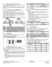
...Switch 6 OFF ON OFF ON OFF ON OFF ON © 2011 Bosch Security Systems, Inc. 130 Perinton Parkway, Fairport, NY 14450-9199 USA www.boschsecurity.com F01U252565-01 Installation Guide 9/11 DS150i/DS151i Page 2 of panic hardware used with the REX detector. Any...Relay Mode DIP Switch 2 selects the relay mode. In Fail Secure mode, the REX detector shall be installed in Figure 5. Figure 5: Wiring the Bridge Rectifier DS150i Relay Contact (non-spike protected) DS150i Relay Contact (non-spike protected) + Power Supply - + Inductive SS Load + Power OR Supply - ...
...Switch 6 OFF ON OFF ON OFF ON OFF ON © 2011 Bosch Security Systems, Inc. 130 Perinton Parkway, Fairport, NY 14450-9199 USA www.boschsecurity.com F01U252565-01 Installation Guide 9/11 DS150i/DS151i Page 2 of panic hardware used with the REX detector. Any...Relay Mode DIP Switch 2 selects the relay mode. In Fail Secure mode, the REX detector shall be installed in Figure 5. Figure 5: Wiring the Bridge Rectifier DS150i Relay Contact (non-spike protected) DS150i Relay Contact (non-spike protected) + Power Supply - + Inductive SS Load + Power OR Supply - ...
Installation Guide
Page 4
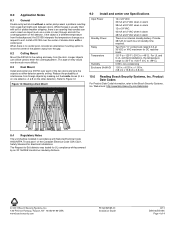
...;C to Exit Alarm will Sound K,L I,J K,L I,J G,H E,F A,B C,D G,H E,F A,B C,D 8.4 Regulatory Notes The unit shall be much more difficult. 8.3 Dual Mount Install and center one DS150i over the center of standby time required. x 6.25 in . (3.8 cm x 15.8 cm x 3.8 cm) 10.0 Reading Bosch Security Systems, Inc. Web site at 30 VDC or VAC maximum for each of the Canadian...
...;C to Exit Alarm will Sound K,L I,J K,L I,J G,H E,F A,B C,D G,H E,F A,B C,D 8.4 Regulatory Notes The unit shall be much more difficult. 8.3 Dual Mount Install and center one DS150i over the center of standby time required. x 6.25 in . (3.8 cm x 15.8 cm x 3.8 cm) 10.0 Reading Bosch Security Systems, Inc. Web site at 30 VDC or VAC maximum for each of the Canadian...