Installation Guide
Page 1
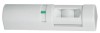
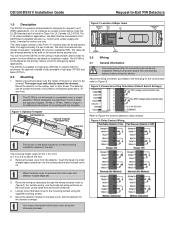
... listed installation applications, the REX shall be programmed to fail safe or fail secure during a power loss. The latch time features two modes of a small ...cover (at the same end as the primary means of two Form "C" contacts that can mount the DS150i on the ceiling or wall and aim and/or mask its correct mounting orientation relative to Figure 3). Remove...). 4. Refer to the mounting surface using the optional trimplate (TP160 or TP161). Figure 1: Optional Trimplate DS150i/DS151i DOOR DOOR Optional Trimplate (TP160/TP161) Gang box Refer to Figure 4 to completely cover a single...
... listed installation applications, the REX shall be programmed to fail safe or fail secure during a power loss. The latch time features two modes of a small ...cover (at the same end as the primary means of two Form "C" contacts that can mount the DS150i on the ceiling or wall and aim and/or mask its correct mounting orientation relative to Figure 3). Remove...). 4. Refer to the mounting surface using the optional trimplate (TP160 or TP161). Figure 1: Optional Trimplate DS150i/DS151i DOOR DOOR Optional Trimplate (TP160/TP161) Gang box Refer to Figure 4 to completely cover a single...
Installation Guide
Page 2
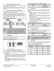
...Refer to configure the operation of panic hardware used with the REX detector. Table 2: Relay Mode DIP Switch Settings Switch 2 Function OFF Fail Secure ON Fail Safe (Default) Refer to the detector, use a bridge rectifier/diode may reduce the lifetime of time the relay can cause unwanted ...ON 64 ON ON Switch 6 OFF ON OFF ON OFF ON OFF ON © 2011 Bosch Security Systems, Inc. 130 Perinton Parkway, Fairport, NY 14450-9199 USA www.boschsecurity.com F01U252565-01 Installation Guide 9/11 DS150i/DS151i Page 2 of latch time, or if latch time is enabled or disabled. 3.2 EMF...
...Refer to configure the operation of panic hardware used with the REX detector. Table 2: Relay Mode DIP Switch Settings Switch 2 Function OFF Fail Secure ON Fail Safe (Default) Refer to the detector, use a bridge rectifier/diode may reduce the lifetime of time the relay can cause unwanted ...ON 64 ON ON Switch 6 OFF ON OFF ON OFF ON OFF ON © 2011 Bosch Security Systems, Inc. 130 Perinton Parkway, Fairport, NY 14450-9199 USA www.boschsecurity.com F01U252565-01 Installation Guide 9/11 DS150i/DS151i Page 2 of latch time, or if latch time is enabled or disabled. 3.2 EMF...
Installation Guide
Page 4
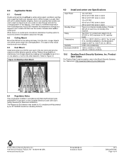
..., Inc. x 6.25 in . (3.8 cm x 15.8 cm x 3.8 cm) 10.0 Reading Bosch Security Systems, Inc. If the object is an opening that might exist between doors. Install a DS150i over each hour of standby time required. Provide 38 mAh for UL compliance while powered by an XF ...without a center post present a problem resulting from foreign objects by AmSeco. © 2011 Bosch Security Systems, Inc. 130 Perinton Parkway, Fairport, NY 14450-9199 USA www.boschsecurity.com F01U252565-01 Installation Guide 9/11 DS150i/DS151i Page 4 of 4 Longer objects can use to insert an object (such as a...
..., Inc. x 6.25 in . (3.8 cm x 15.8 cm x 3.8 cm) 10.0 Reading Bosch Security Systems, Inc. If the object is an opening that might exist between doors. Install a DS150i over each hour of standby time required. Provide 38 mAh for UL compliance while powered by an XF ...without a center post present a problem resulting from foreign objects by AmSeco. © 2011 Bosch Security Systems, Inc. 130 Perinton Parkway, Fairport, NY 14450-9199 USA www.boschsecurity.com F01U252565-01 Installation Guide 9/11 DS150i/DS151i Page 4 of 4 Longer objects can use to insert an object (such as a...