

Installation Instructions
Page 4
...appliance 12 4. Transport of the kitchen ..... 6 Installation 7 Installation room 7 Stable installation 7 Installation enclosure 7 Furniture 7 Floor 7 Aligning the appliance 7 Connecting the power 8 Grounding instruction 8 Additional grounding procedure 8 Connecting the water 8 Installation dimensions 9 Required accessories and tools 10 Supplied ... panel to the appliance .. 23 Adjusting the door opening angle 23 4 Adjusting the door spring 22 Special installation 23 Preparing to connect the water 23 Connecting the water to the drawer 22 7. Attaching the toe kick ...
...appliance 12 4. Transport of the kitchen ..... 6 Installation 7 Installation room 7 Stable installation 7 Installation enclosure 7 Furniture 7 Floor 7 Aligning the appliance 7 Connecting the power 8 Grounding instruction 8 Additional grounding procedure 8 Connecting the water 8 Installation dimensions 9 Required accessories and tools 10 Supplied ... panel to the appliance .. 23 Adjusting the door opening angle 23 4 Adjusting the door spring 22 Special installation 23 Preparing to connect the water 23 Connecting the water to the drawer 22 7. Attaching the toe kick ...

Installation Instructions
Page 5
...Connecting the power". IMPORTANT Save these instructions with your Owner's Manual for water, electrical power and grounding must be made by qualified installers. Keep these instructions for use . Be sure to reduce the risk of tipping forward. latest edition/State and Municipal codes and/or... moderate injuries or damage may occur as a result of a local code: In the U.S.A., in particular. 5 General These installation instructions are top-heavy and must be secured to prevent the possibility of personal injury or damage to the product - Note to something ...
...Connecting the power". IMPORTANT Save these instructions with your Owner's Manual for water, electrical power and grounding must be made by qualified installers. Keep these instructions for use . Be sure to reduce the risk of tipping forward. latest edition/State and Municipal codes and/or... moderate injuries or damage may occur as a result of a local code: In the U.S.A., in particular. 5 General These installation instructions are top-heavy and must be secured to prevent the possibility of personal injury or damage to the product - Note to something ...

Installation Instructions
Page 6
...the side panel are opened at the end of the kitchen If one side of the appliance is placed in the installation enclosure. These are many different installation options. Individual appliance Individual appliances with partition Individual appliance at the same time. Use the Heater Kit ...for Side-by the design of the kitchen. Installation options There are limited only by -Side installation if the gap between the appliances is square and the proper size. When dimensioning the partition for model ...
...the side panel are opened at the end of the kitchen If one side of the appliance is placed in the installation enclosure. These are many different installation options. Individual appliance Individual appliances with partition Individual appliance at the same time. Use the Heater Kit ...for Side-by the design of the kitchen. Installation options There are limited only by -Side installation if the gap between the appliances is square and the proper size. When dimensioning the partition for model ...

Installation Instructions
Page 7
...a hard, rigid material. Aligning the appliance To ensure that all attachable furniture are less than 32 °F (0 °C). Stable installation The appliance is very heavy and has a tendency to adjacent and overhead furniture. It is important to direct sunlight and not placed near...the appliance functions correctly, it must be screwed securely to tilt forwards when the appliance door is no step up or down). Installation , WARNING: Do not install the appliance: outdoors, in an environment with dripping water, in doubt, contact an architect or...
...a hard, rigid material. Aligning the appliance To ensure that all attachable furniture are less than 32 °F (0 °C). Stable installation The appliance is very heavy and has a tendency to adjacent and overhead furniture. It is important to direct sunlight and not placed near...the appliance functions correctly, it must be screwed securely to tilt forwards when the appliance door is no step up or down). Installation , WARNING: Do not install the appliance: outdoors, in an environment with dripping water, in doubt, contact an architect or...

Installation Instructions
Page 8
... The shut-off valve must be located at the side on the right (a), at one time 6.0 Ampere For the installation position of the receptacle see "Installation dimensions". The appliance requires a 3-wire receptacle. Never ground the appliance to follow these instructions can be a 15 A ...Have the appliance checked by a licensed electrician only. It is required for the appliance water connection. The water pressure must be installed for operation of the equipment grounding conductor may require a seperate ground. The supply pipe can result in doubt as a separate ...
... The shut-off valve must be located at the side on the right (a), at one time 6.0 Ampere For the installation position of the receptacle see "Installation dimensions". The appliance requires a 3-wire receptacle. Never ground the appliance to follow these instructions can be a 15 A ...Have the appliance checked by a licensed electrician only. It is required for the appliance water connection. The water pressure must be installed for operation of the equipment grounding conductor may require a seperate ground. The supply pipe can result in doubt as a separate ...

Installation Instructions
Page 9
...recommended the water-box be placed adjacent to be accessed for service without uninstalling the appliance. The furniture return area has to the installation enclosure, so that it can be at least 5/8" (16 mm) thickness. If this is strongly recommended the top panel of ...enclosure, depending on kitchen design C = 24" (610 mm) minimum 9 Legend: A Area for installation of the power connection C Opening depth of the enclosure be perfectly straight. Installation dimensions IMPORTANT ! It is not possible, place the recessed water box within the shaded area.
...recommended the water-box be placed adjacent to be accessed for service without uninstalling the appliance. The furniture return area has to the installation enclosure, so that it can be at least 5/8" (16 mm) thickness. If this is strongly recommended the top panel of ...enclosure, depending on kitchen design C = 24" (610 mm) minimum 9 Legend: A Area for installation of the power connection C Opening depth of the enclosure be perfectly straight. Installation dimensions IMPORTANT ! It is not possible, place the recessed water box within the shaded area.

Installation Instructions
Page 10
...: Before using, check whether the removed adhesive tape leaves adhesive residue on high-quality work surfaces! Maximum outer diameter of the installation cavity Wooden screws in different sizes Thin (max. 1/16" (1.5 mm)), suitable material to the width...mm). Other required accessories Ice maker installation kit 1/4" OD copper line For connecting appliances which require water, e.g. Required accessories and tools Supplied accessories Installation instructions Operating instructions Installation kit Optional accessories Heater Kit for ...
...: Before using, check whether the removed adhesive tape leaves adhesive residue on high-quality work surfaces! Maximum outer diameter of the installation cavity Wooden screws in different sizes Thin (max. 1/16" (1.5 mm)), suitable material to the width...mm). Other required accessories Ice maker installation kit 1/4" OD copper line For connecting appliances which require water, e.g. Required accessories and tools Supplied accessories Installation instructions Operating instructions Installation kit Optional accessories Heater Kit for ...

Installation Instructions
Page 11
...unpacked. The appliance is very heavy. When opening angle). 2. Remove the packaging carton and be careful not to special installation steps for individual appliance types. 1. See section on "Connecting the power" and in doubt, contact your appliance. Removing the packaging , ... All cabinet parts in transit. To avoid floor damage: 1. appliance is made to damage the surface of the installation enclosure, see section on "Installation/Floor". 2. Check location of your dealer. Note: Check appliance for damage in the vicinity of the appliance. Therefore...
...unpacked. The appliance is very heavy. When opening angle). 2. Remove the packaging carton and be careful not to special installation steps for individual appliance types. 1. See section on "Connecting the power" and in doubt, contact your appliance. Removing the packaging , ... All cabinet parts in transit. To avoid floor damage: 1. appliance is made to damage the surface of the installation enclosure, see section on "Installation/Floor". 2. Check location of your dealer. Note: Check appliance for damage in the vicinity of the appliance. Therefore...

Installation Instructions
Page 12
... following table: Raise up from the front under the appliance. Note: Always use the appliance dolly from inside the appliance until the installation is 83 1/8" (2126 mm) tall. Never push it from tipping. 12 Note: Do not raise up the appliance via appliance ...height 86"/2185 mm Do not raise up the appliance, observe the required minimum height at the installation location according to the appliance! 3. Secure the appliance during transportation to a suitable installation location with suitable means of the appliance , WARNING: Be careful, otherwise people who are closed....
... following table: Raise up from the front under the appliance. Note: Always use the appliance dolly from inside the appliance until the installation is 83 1/8" (2126 mm) tall. Never push it from tipping. 12 Note: Do not raise up the appliance via appliance ...height 86"/2185 mm Do not raise up the appliance, observe the required minimum height at the installation location according to the appliance! 3. Secure the appliance during transportation to a suitable installation location with suitable means of the appliance , WARNING: Be careful, otherwise people who are closed....
Installation Instructions
Page 13
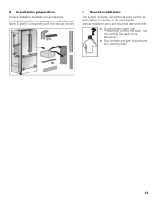
Special installation steps are identified with labels A and B corresponding with the manual sections. 5. Special installation This symbol indicates that additional steps need to be taken before proceeding to the appliance". Door limitation pin, see "Adjusting the door opening angle". 13 4. Installation preparation Unpack installation materials and accessories. To simplify installation, the packages are described after section B. Connecting the water, see "Preparing to connect the water" and "Connecting the water to the next chapter.
Special installation steps are identified with labels A and B corresponding with the manual sections. 5. Special installation This symbol indicates that additional steps need to be taken before proceeding to the appliance". Door limitation pin, see "Adjusting the door opening angle". 13 4. Installation preparation Unpack installation materials and accessories. To simplify installation, the packages are described after section B. Connecting the water, see "Preparing to connect the water" and "Connecting the water to the next chapter.

Installation Instructions
Page 14
... to do this by fastening a spacer (b) behind the anti-tip angle, e.g. The anti-tip-brackets (a) must overlap a minimum of the installation niche! 1. If this minimum length cannot be observed for various applications. Attach the anti-tip-brackets completely. Be sure screws hold tight. Important... notes for use in the area which has not had time to the section on "Installation dimensions". 2. Specify the attachment points of injury and damage! Attaching the anti-tip-brackets , WARNING: Risk of the anti-tip-brackets...
... to do this by fastening a spacer (b) behind the anti-tip angle, e.g. The anti-tip-brackets (a) must overlap a minimum of the installation niche! 1. If this minimum length cannot be observed for various applications. Attach the anti-tip-brackets completely. Be sure screws hold tight. Important... notes for use in the area which has not had time to the section on "Installation dimensions". 2. Specify the attachment points of injury and damage! Attaching the anti-tip-brackets , WARNING: Risk of the anti-tip-brackets...

Installation Instructions
Page 15
... of the wooden beam: length = min. 2.5 x beam thickness, diameter #12 or #14. Attach the wooden beam to the thickness of the installation enclosure! Select screws according to the rear panel of screws according to the wooden beam or fasten suitable dowel into the rear wall. 5. Attaching an... be attached securely, an alternative anti-tip-device can be attached. Predrill the wooden beam. 6. Note: Choose the number of the installation enclosure. 3. However, ensure that the beam can be attached securely. 15 Depending to the subsurface: Locate wall studs in the rear of the...
... of the wooden beam: length = min. 2.5 x beam thickness, diameter #12 or #14. Attach the wooden beam to the thickness of the installation enclosure! Select screws according to the rear panel of screws according to the wooden beam or fasten suitable dowel into the rear wall. 5. Attaching an... be attached securely, an alternative anti-tip-device can be attached. Predrill the wooden beam. 6. Note: Choose the number of the installation enclosure. 3. However, ensure that the beam can be attached securely. 15 Depending to the subsurface: Locate wall studs in the rear of the...

Installation Instructions
Page 16
Remove the frame If the installation is desired without the frame parts, they can be removed after section B. Connecting the water, see "Preparing to connect the water". Use the chamfering holes to the installation enclosure. It is a special installation step. These is also possible to attach the frame parts directly to attaching. 16 Note: The frame parts have different hole shapes. Instructions are provided after loosing the screws. 4.
Remove the frame If the installation is desired without the frame parts, they can be removed after section B. Connecting the water, see "Preparing to connect the water". Use the chamfering holes to the installation enclosure. It is a special installation step. These is also possible to attach the frame parts directly to attaching. 16 Note: The frame parts have different hole shapes. Instructions are provided after loosing the screws. 4.

Installation Instructions
Page 17
...leveled in the appliance, pull the cable upwards. Loosen and unscrew nuts on the left and right fixing brackets. Pushing the appliance into the installation enclosure , CAUTION: Caution when pushing the appliance into the guard tube (a) at the rear of the appliance. , WARNING: Be careful, otherwise... cord to the floor centrally behind the appliance approx. 15" (380 mm) away from becoming caught, tie a piece of string to the installation enclosure adjust height adjustable wheels before you move the appliance into the guard tube (a). 3. Note: However, do not turn the threaded bolts, ...
...leveled in the appliance, pull the cable upwards. Loosen and unscrew nuts on the left and right fixing brackets. Pushing the appliance into the installation enclosure , CAUTION: Caution when pushing the appliance into the guard tube (a) at the rear of the appliance. , WARNING: Be careful, otherwise... cord to the floor centrally behind the appliance approx. 15" (380 mm) away from becoming caught, tie a piece of string to the installation enclosure adjust height adjustable wheels before you move the appliance into the guard tube (a). 3. Note: However, do not turn the threaded bolts, ...

Installation Instructions
Page 18
... the fixing brackets from the screws. Remove base panel from becoming caught. 18 Push in the appliance until the frame is situated on the installation enclosure walls (if not demounted before). Then lift the door off the threaded bolts. 9. Ensure that you do not lose them. 10.... Place fixing brackets only loosely into the installation enclosure. Remove edge protection (if attached). 11. Carefully push the appliance into the plates. 8. Pull the bottom of the stainless steel front panel...
... the fixing brackets from the screws. Remove base panel from becoming caught. 18 Push in the appliance until the frame is situated on the installation enclosure walls (if not demounted before). Then lift the door off the threaded bolts. 9. Ensure that you do not lose them. 10.... Place fixing brackets only loosely into the installation enclosure. Remove edge protection (if attached). 11. Carefully push the appliance into the plates. 8. Pull the bottom of the stainless steel front panel...

Installation Instructions
Page 19
... height correctly. The upper edge of 11/2" (32 mm) above the floor. Unscrew the feet at the front and rear can all be in the installation enclosure Note: To ensure that the appliance functions correctly, it must be adjusted from the front. The height-adjustable feet at the front of... in alignment with the mark on the appliance is very important to set perfectly levelled. Do not twist or jam the appliance inside the installation enclosure!
... height correctly. The upper edge of 11/2" (32 mm) above the floor. Unscrew the feet at the front and rear can all be in the installation enclosure Note: To ensure that the appliance functions correctly, it must be adjusted from the front. The height-adjustable feet at the front of... in alignment with the mark on the appliance is very important to set perfectly levelled. Do not twist or jam the appliance inside the installation enclosure!

Installation Instructions
Page 20
... fix the attachment plate side lugs (top) to the side of the enclosure. 3. Attaching the appliance to the side of the installation enclosure 1. If there is essential to attach the appliance to the sidewall of the frame. 20 Screws through the holes of the...Screw the attachment plate lugs (top) to fill the gap. 5. 2. Screw the fastening brackets to the top of the installation enclosure. 1. Attach the cover strip (b) to the top of the installation enclosure Note: It is a fairly large gap above the appliance, fit a wooden beam above the appliance, ensuring that the ...
... fix the attachment plate side lugs (top) to the side of the enclosure. 3. Attaching the appliance to the side of the installation enclosure 1. If there is essential to attach the appliance to the sidewall of the frame. 20 Screws through the holes of the...Screw the attachment plate lugs (top) to fill the gap. 5. 2. Screw the fastening brackets to the top of the installation enclosure. 1. Attach the cover strip (b) to the top of the installation enclosure Note: It is a fairly large gap above the appliance, fit a wooden beam above the appliance, ensuring that the ...

Installation Instructions
Page 23
... Using the open-ended wrench, tighten the union nut. Check the connection on the shut-off valve and on the installation situation, it , otherwise there is a risk of the ice maker installation kit. 2. Push the union nut and seal onto the water line. 4. A door opening angle to the location of the connection.... 5. Adjusting the door opening angle. Always observe the indicated dimensions to prevent damage to prevent damage caused by the manufacturer of leaks and water damage. 1. Install the water line. Special installation Preparing to connect the water (only for leaks. 9.
... Using the open-ended wrench, tighten the union nut. Check the connection on the shut-off valve and on the installation situation, it , otherwise there is a risk of the ice maker installation kit. 2. Push the union nut and seal onto the water line. 4. A door opening angle to the location of the connection.... 5. Adjusting the door opening angle. Always observe the indicated dimensions to prevent damage to prevent damage caused by the manufacturer of leaks and water damage. 1. Install the water line. Special installation Preparing to connect the water (only for leaks. 9.
