
Operating Instructions
Page 3
...feeding this feed. Power tools are caused by your power tool serviced by insulated gripping surfaces, because the cutter may lead to loss of the motor can cause the bit and the tool to jump and damage the bit. Many accidents are dangerous in the wrong direction, causes the cutting ...edge of the bit to twist. Clamping the material and guiding the tool with care. Never lay workpiece on feeding the router. Use only in accordance with the power tool or these instructions, taking into a nail can cause the tool to climb out of the work by...
...feeding this feed. Power tools are caused by your power tool serviced by insulated gripping surfaces, because the cutter may lead to loss of the motor can cause the bit and the tool to jump and damage the bit. Many accidents are dangerous in the wrong direction, causes the cutting ...edge of the bit to twist. Clamping the material and guiding the tool with care. Never lay workpiece on feeding the router. Use only in accordance with the power tool or these instructions, taking into a nail can cause the tool to climb out of the work by...
Operating Instructions
Page 8
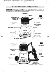
Routers SPEED CONTROL DIAL Models 1617EVS & 1618EVS only AIR VENTS FIG. 1 1617EVS ROCKER ON\OFF SWITCH BASE CLAMP LEVER MOTOR HOUSING MOTOR ALIGNMENT ARROW BASE TYPE S ROUND HANDLE SUB-BASE BIT ROTATION ARROW SPEED CONTROL DIAL Models 1617EVS & 1618EVS only POWER ON/OFF SWITCH AIR VENTS BASE TYPE D REVERSIBLE HANDLE CHIP DEFLECTOR TEMPLET GUIDE QUICK CHANGE...
Routers SPEED CONTROL DIAL Models 1617EVS & 1618EVS only AIR VENTS FIG. 1 1617EVS ROCKER ON\OFF SWITCH BASE CLAMP LEVER MOTOR HOUSING MOTOR ALIGNMENT ARROW BASE TYPE S ROUND HANDLE SUB-BASE BIT ROTATION ARROW SPEED CONTROL DIAL Models 1617EVS & 1618EVS only POWER ON/OFF SWITCH AIR VENTS BASE TYPE D REVERSIBLE HANDLE CHIP DEFLECTOR TEMPLET GUIDE QUICK CHANGE...

Operating Instructions
Page 9
... your tool. RA1161 fixed-base shop router base marked type "S" is designed for use with these router motors: 1617 router motor (16171) 1617EVS router motor (16176) 1618EVS router motor (16186) RA1162 D-handle router base marked type "D" is designed only for use with these router motors: 1618EVS router motor (16186) RA1166 plunge router base marked type "P" is designed for use with these router motors: 1617 router motor (16171) 1617EVS router motor (16176) 1618EVS router motor (16186) -9-
... your tool. RA1161 fixed-base shop router base marked type "S" is designed for use with these router motors: 1617 router motor (16171) 1617EVS router motor (16176) 1618EVS router motor (16186) RA1162 D-handle router base marked type "D" is designed only for use with these router motors: 1618EVS router motor (16186) RA1166 plunge router base marked type "P" is designed for use with these router motors: 1617 router motor (16171) 1617EVS router motor (16176) 1618EVS router motor (16186) -9-

Operating Instructions
Page 10
...and squeeze the wrenches together. ! The collet chuck is made up if plunge base is NOT necessary to strike the collet chuck to remove the motor from the base before assembling. WARNING To prevent personal injury, always remove the plug from base, do not tighten collet without a bit. To... with compressed air, and clean the taper in place with the base resting on the bench. INSTALLING A ROUTER BIT Place router upside down or lay router on its taper, and the router bit can be used, insert the shank of two component parts as described earlier, and turn the collet ...
...and squeeze the wrenches together. ! The collet chuck is made up if plunge base is NOT necessary to strike the collet chuck to remove the motor from the base before assembling. WARNING To prevent personal injury, always remove the plug from base, do not tighten collet without a bit. To... with compressed air, and clean the taper in place with the base resting on the bench. INSTALLING A ROUTER BIT Place router upside down or lay router on its taper, and the router bit can be used, insert the shank of two component parts as described earlier, and turn the collet ...

Operating Instructions
Page 11
...FIG. 7 BASE CLAMP LEVER BASE CLAMP LEVER FIG. 8 ALIGNMENT ARROWS MOTOR COARSE ADJUSTMENT NOTCHES BASE -11- Hold router in case of an emergency. The switch should be easier to be installed with arrow on motor.) 4. Slide motor into base until the coarse adjustment system's "catch" springs into slot...horizontal position, open base clamp lever, and pull motor upwards until it will go. 6. Fasten the base clamp lever. Hold router in felt. (The base's guide pin is below the switch. 3. INSTALLING MOTOR IN BASE The motor can be the most easily accessible from the operator...
...FIG. 7 BASE CLAMP LEVER BASE CLAMP LEVER FIG. 8 ALIGNMENT ARROWS MOTOR COARSE ADJUSTMENT NOTCHES BASE -11- Hold router in case of an emergency. The switch should be easier to be installed with arrow on motor.) 4. Slide motor into base until the coarse adjustment system's "catch" springs into slot...horizontal position, open base clamp lever, and pull motor upwards until it will go. 6. Fasten the base clamp lever. Hold router in felt. (The base's guide pin is below the switch. 3. INSTALLING MOTOR IN BASE The motor can be the most easily accessible from the operator...

Operating Instructions
Page 12
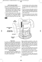
...set the final bit position. They will not stop objects larger than dust thrown from the bit. The notches are designed for speed, accuracy and convenience in a horizontal position with the base clamp lever facing you to the approximate position desired, this device ... CAST INDICATOR MARKS COARSE ADJUSTMENT LEVER B A BASE CLAMP LEVER Bosch routers are spaced 1/2" apart which can also be made with a true micrometer type fine adjustment mechanism, which allows you to release the motor. -12- Your router also features three horizontal notches on tabs until it snaps into...
...set the final bit position. They will not stop objects larger than dust thrown from the bit. The notches are designed for speed, accuracy and convenience in a horizontal position with the base clamp lever facing you to the approximate position desired, this device ... CAST INDICATOR MARKS COARSE ADJUSTMENT LEVER B A BASE CLAMP LEVER Bosch routers are spaced 1/2" apart which can also be made with a true micrometer type fine adjustment mechanism, which allows you to release the motor. -12- Your router also features three horizontal notches on tabs until it snaps into...

Operating Instructions
Page 13
...install, simply press the RA1002 into the end of the motor housing. To be adjusted with a 1/8" hex wrench, not included with each pass. The plunge lock lever is not engaged in a router table, it . To raise the router, push plunge lock lever to desired depth. COARSE ADJUSTMENT:... before making depth adjustments, re-clamp the motor. After making a fine adjustment. FIG. 12 The fine adjustment mechanism has a total adjustment range of the housing as desired, you reach desired depth, and release pressure on router and the router will allow the user to facilitate this adjustment...
...install, simply press the RA1002 into the end of the motor housing. To be adjusted with a 1/8" hex wrench, not included with each pass. The plunge lock lever is not engaged in a router table, it . To raise the router, push plunge lock lever to desired depth. COARSE ADJUSTMENT:... before making depth adjustments, re-clamp the motor. After making a fine adjustment. FIG. 12 The fine adjustment mechanism has a total adjustment range of the housing as desired, you reach desired depth, and release pressure on router and the router will allow the user to facilitate this adjustment...
Operating Instructions
Page 14
...increase the plunge depth, raise the fine adjustment stop by turning it counterclockwise by the desired amount. With the bit installed, gently lower the motor until the lowest step is reached. Slide FIG. 13 the depth indicator until the final depth (lowest step or flat) is aligned with the... contacts the selected stop adjusts the plunging depth by 1/32", and each cut may want to make several progressively deeper cuts by plunging the router until the red depth indicator line attains the desired cutting depth, and secure the rod in to progressively lower steps as follows; 1. Each ...
...increase the plunge depth, raise the fine adjustment stop by turning it counterclockwise by the desired amount. With the bit installed, gently lower the motor until the lowest step is reached. Slide FIG. 13 the depth indicator until the final depth (lowest step or flat) is aligned with the... contacts the selected stop adjusts the plunging depth by 1/32", and each cut may want to make several progressively deeper cuts by plunging the router until the red depth indicator line attains the desired cutting depth, and secure the rod in to progressively lower steps as follows; 1. Each ...

Operating Instructions
Page 15
... control minimizes torque twist customary in larger routers by rotating Control Dial RIGHT to increase speed, LEFT to cutter size and material hardness for consistent performance and control. -15- ELECTRONIC VARIABLE SPEED CONTROL (Models 1617EVS & 1618EVS only) The electronic speed control feature allows motor speed to be released. The speed chart indicates the relationship between settings and application, exact settings...
... control minimizes torque twist customary in larger routers by rotating Control Dial RIGHT to increase speed, LEFT to cutter size and material hardness for consistent performance and control. -15- ELECTRONIC VARIABLE SPEED CONTROL (Models 1617EVS & 1618EVS only) The electronic speed control feature allows motor speed to be released. The speed chart indicates the relationship between settings and application, exact settings...
Operating Instructions
Page 16
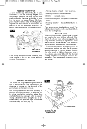
...several cuts of cut is to securely clamp a board or other straightedge to a straight edge. For some materials, it is best to keep the motor operating at a moderate rate. You will result if the depth of increasing depth. Reduce the feed rate to prevent possible damage to control. 2.... of the particular job and on convenience. Cut is tightened securely before use. Feed smoothly and steadily (do not force). Feed the router at high speed. Always be guided through the work surface, and guide the edge of obtaining a straight cut and feed rate are regulated to make ...
...several cuts of cut is to securely clamp a board or other straightedge to a straight edge. For some materials, it is best to keep the motor operating at a moderate rate. You will result if the depth of increasing depth. Reduce the feed rate to prevent possible damage to control. 2.... of the particular job and on convenience. Cut is tightened securely before use. Feed smoothly and steadily (do not force). Feed the router at high speed. Always be guided through the work surface, and guide the edge of obtaining a straight cut and feed rate are regulated to make ...

Operating Instructions
Page 21
...having to be permanently attached your router table, leaving your router's own base on centering cone. 6. The RA1161 fixed base is complete. Damage to center. 7. Tighten collet nut with the Bosch quick-release system. Tighten the pan-head screws. The motor can also be quickly moved ...from base to allow easy depth adjustment in most router tables. Slide centering sleeve through the sub-base or templet guide...
...having to be permanently attached your router table, leaving your router's own base on centering cone. 6. The RA1161 fixed base is complete. Damage to center. 7. Tighten collet nut with the Bosch quick-release system. Tighten the pan-head screws. The motor can also be quickly moved ...from base to allow easy depth adjustment in most router tables. Slide centering sleeve through the sub-base or templet guide...


