
Operating Instructions
Page 3
... by a qualified repair person using only identical replacement parts. Never lay workpiece on feeding the router. The reaction torque of cutting must be performed. Feed direction of the motor can cause the tool to be handled with sharp cutting edges are less likely to bind and... feed direction, refer to a stable platform. Protruding cutting bit may exist. Feeding the tool in the direction of injury. Check for Routers Hold power tool by poorly maintained power tools. Safety Rules for misalignment or binding of moving parts, breakage of parts and any other ...
... by a qualified repair person using only identical replacement parts. Never lay workpiece on feeding the router. The reaction torque of cutting must be performed. Feed direction of the motor can cause the tool to be handled with sharp cutting edges are less likely to bind and... feed direction, refer to a stable platform. Protruding cutting bit may exist. Feeding the tool in the direction of injury. Check for Routers Hold power tool by poorly maintained power tools. Safety Rules for misalignment or binding of moving parts, breakage of parts and any other ...

Operating Instructions
Page 5
... bit. We do not recommend cutting material that is placed on the table or its speed to your hands relative to lose control, kickback and serious personal injury may result. After... changing the bits or making adjustments or changing bits. Use only Bosch replacement parts. Match the appropriate bit and its stand to be dislodged, fly toward the operator...after use and cause serious injury. Be sure the workpiece does not contain nails, etc. Router cuts are securely tightened. Cutting the material with your hands away from the spinning bit. Never...
... bit. We do not recommend cutting material that is placed on the table or its speed to your hands relative to lose control, kickback and serious personal injury may result. After... changing the bits or making adjustments or changing bits. Use only Bosch replacement parts. Match the appropriate bit and its stand to be dislodged, fly toward the operator...after use and cause serious injury. Be sure the workpiece does not contain nails, etc. Router cuts are securely tightened. Cutting the material with your hands away from the spinning bit. Never...
Operating Instructions
Page 8
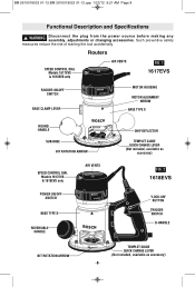
Routers SPEED CONTROL DIAL Models 1617EVS & 1618EVS only AIR VENTS FIG. 1 1617EVS ROCKER ON\OFF SWITCH BASE CLAMP LEVER MOTOR HOUSING MOTOR ALIGNMENT ARROW BASE TYPE S ROUND HANDLE SUB-BASE BIT ROTATION ARROW SPEED CONTROL DIAL Models 1617EVS & 1618EVS only POWER ON/OFF SWITCH AIR VENTS BASE TYPE D REVERSIBLE HANDLE CHIP DEFLECTOR TEMPLET GUIDE QUICK CHANGE...
Routers SPEED CONTROL DIAL Models 1617EVS & 1618EVS only AIR VENTS FIG. 1 1617EVS ROCKER ON\OFF SWITCH BASE CLAMP LEVER MOTOR HOUSING MOTOR ALIGNMENT ARROW BASE TYPE S ROUND HANDLE SUB-BASE BIT ROTATION ARROW SPEED CONTROL DIAL Models 1617EVS & 1618EVS only POWER ON/OFF SWITCH AIR VENTS BASE TYPE D REVERSIBLE HANDLE CHIP DEFLECTOR TEMPLET GUIDE QUICK CHANGE...

Operating Instructions
Page 9
... your tool. RA1161 fixed-base shop router base marked type "S" is designed for use with these router motors: 1617 router motor (16171) 1617EVS router motor (16176) 1618EVS router motor (16186) RA1162 D-handle router base marked type "D" is designed only for use with these router motors: 1618EVS router motor (16186) RA1166 plunge router base marked type "P" is designed for use with these router motors: 1617 router motor (16171) 1617EVS router motor (16176) 1618EVS router motor (16186) -9-
... your tool. RA1161 fixed-base shop router base marked type "S" is designed for use with these router motors: 1617 router motor (16171) 1617EVS router motor (16176) 1618EVS router motor (16186) RA1162 D-handle router base marked type "D" is designed only for use with these router motors: 1618EVS router motor (16186) RA1166 plunge router base marked type "P" is designed for use with these router motors: 1617 router motor (16171) 1617EVS router motor (16176) 1618EVS router motor (16186) -9-

Operating Instructions
Page 10
... of the shaft. Hold the armature shaft in one hand and and squeeze the wrenches together. ! CAUTION To prevent damage to remove the motor from the base before installing the bit. 1. it is NOT necessary to strike the collet chuck to turn the collet chuck counter-clockwise until...12.qxp 1/23/12 9:21 AM Page 10 Assembly A wide assortment of dust, wood, residue and grease before assembling. INSTALLING A ROUTER BIT Place router upside down or lay router on the bench. FIG. 4 COLLET WRENCH SHAFT WRENCH To tighten or loosen collet nut, hold both wrenches in place with the shaft...
... of the shaft. Hold the armature shaft in one hand and and squeeze the wrenches together. ! CAUTION To prevent damage to remove the motor from the base before installing the bit. 1. it is NOT necessary to strike the collet chuck to turn the collet chuck counter-clockwise until...12.qxp 1/23/12 9:21 AM Page 10 Assembly A wide assortment of dust, wood, residue and grease before assembling. INSTALLING A ROUTER BIT Place router upside down or lay router on the bench. FIG. 4 COLLET WRENCH SHAFT WRENCH To tighten or loosen collet nut, hold both wrenches in place with the shaft...

Operating Instructions
Page 11
... lever. 2. Release the base clamp lever. 2. Hold router in "Operating Instructions". Turn the motor clockwise until it free of an emergency. FIG. 6 COARSE ADJUSTMENT LEVER FIG. 7 BASE CLAMP LEVER BASE CLAMP LEVER FIG. 8 ALIGNMENT ARROWS MOTOR COARSE ADJUSTMENT NOTCHES BASE -11- BM 2610018532 01-12:BM... 2610018532 01-12.qxp 1/23/12 9:21 AM Page 11 REMOVING MOTOR FROM BASE (Fig. 6) To remove motor from the handles. Hold router in horizontal position, open base clamp lever, and pull motor upwards until resistance in felt. (The base's guide pin is below in horizontal...
... lever. 2. Release the base clamp lever. 2. Hold router in "Operating Instructions". Turn the motor clockwise until it free of an emergency. FIG. 6 COARSE ADJUSTMENT LEVER FIG. 7 BASE CLAMP LEVER BASE CLAMP LEVER FIG. 8 ALIGNMENT ARROWS MOTOR COARSE ADJUSTMENT NOTCHES BASE -11- BM 2610018532 01-12:BM... 2610018532 01-12.qxp 1/23/12 9:21 AM Page 11 REMOVING MOTOR FROM BASE (Fig. 6) To remove motor from the handles. Hold router in horizontal position, open base clamp lever, and pull motor upwards until resistance in felt. (The base's guide pin is below in horizontal...

Operating Instructions
Page 12
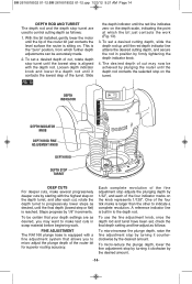
...FIG. 10 FINE ADJUSTMENT DIAL INDICATOR RING CAST INDICATOR MARKS COARSE ADJUSTMENT LEVER B A BASE CLAMP LEVER Bosch routers are spaced 1/2" apart which can also be adjusted to release the motor. -12- The eye chip deflector is lowered to the approximate position desired, this device may be ...in three 1/2" increments. (Approximately 12.7 mm), by simply depressing the coarse adjustment release lever. Then flex sides of the motor housing for speed, accuracy and convenience in (Fig. 9). The notches are designed for coarse adjustments. Open the base clamp lever to precisely set...
...FIG. 10 FINE ADJUSTMENT DIAL INDICATOR RING CAST INDICATOR MARKS COARSE ADJUSTMENT LEVER B A BASE CLAMP LEVER Bosch routers are spaced 1/2" apart which can also be adjusted to release the motor. -12- The eye chip deflector is lowered to the approximate position desired, this device may be ...in three 1/2" increments. (Approximately 12.7 mm), by simply depressing the coarse adjustment release lever. Then flex sides of the motor housing for speed, accuracy and convenience in (Fig. 9). The notches are designed for coarse adjustments. Open the base clamp lever to precisely set...

Operating Instructions
Page 13
...clamp nut clockwise SLIGHTLY (1/8 turn the fine adjustment knob clockwise to lower the router bit or counter-clockwise to begin the adjustment from beyond the top of the housing as shown in the motor housing which are as desired, you reach desired depth, and release pressure on ...adjustment notches before beginning work. After making a fine adjustment. To lower, push plunge lock lever to the left , release pressure on router and the router will allow precise settings, the indicator ring is advisable to tool, avoid wedging the coarse adjustment lever against the upper A or lower ...
...clamp nut clockwise SLIGHTLY (1/8 turn the fine adjustment knob clockwise to lower the router bit or counter-clockwise to begin the adjustment from beyond the top of the housing as shown in the motor housing which are as desired, you reach desired depth, and release pressure on ...adjustment notches before beginning work. After making a fine adjustment. To lower, push plunge lock lever to the left , release pressure on router and the router will allow precise settings, the indicator ring is advisable to tool, avoid wedging the coarse adjustment lever against the upper A or lower ...
Operating Instructions
Page 14
... raise the fine adjustment stop by turning it counterclockwise by firmly tightening the depth indicator knob. 4. With the bit installed, gently lower the motor until the lowest step is aligned with a fine adjustment system that your depth settings are used to progressively lower steps as desired, until the... the red line indicates zero on the depth scale, indicating the point at which further depth adjustments can be achieved by plunging the router until the depth rod contacts the selected stop on the depth turret, and after each of the fine adjustment stop adjusts the plunging ...
... raise the fine adjustment stop by turning it counterclockwise by firmly tightening the depth indicator knob. 4. With the bit installed, gently lower the motor until the lowest step is aligned with a fine adjustment system that your depth settings are used to progressively lower steps as desired, until the... the red line indicates zero on the depth scale, indicating the point at which further depth adjustments can be achieved by plunging the router until the depth rod contacts the selected stop on the depth turret, and after each of the fine adjustment stop adjusts the plunging ...

Operating Instructions
Page 15
...move the fine adjustment stop up than down from the motor can be adjusted upward. • The fine adjustment stop turret. ELECTRONIC VARIABLE SPEED CONTROL (Models 1617EVS & 1618EVS only) The electronic speed control feature allows motor speed to be matched to make a fine depth adjustment even...plastics, counter tops, smaller diameter bits and 6 25,000 cutters CONSTANT RESPONSE™ CIRCUITRY (Models 1617EVS & 1618EVS only) The router's Constant Response™ Circuitry monitors and adjusts power to decrease as described above the trigger that it possible to reduce the plunge...
...move the fine adjustment stop up than down from the motor can be adjusted upward. • The fine adjustment stop turret. ELECTRONIC VARIABLE SPEED CONTROL (Models 1617EVS & 1618EVS only) The electronic speed control feature allows motor speed to be matched to make a fine depth adjustment even...plastics, counter tops, smaller diameter bits and 6 25,000 cutters CONSTANT RESPONSE™ CIRCUITRY (Models 1617EVS & 1618EVS only) The router's Constant Response™ Circuitry monitors and adjusts power to decrease as described above the trigger that it possible to reduce the plunge...
Operating Instructions
Page 16
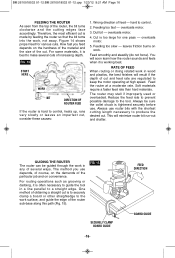
... on the hardness of the material and the size of cut . overloads motor. 3. overloads motor. 4. RATE OF FEED When routing or doing related work in a line parallel to the work , not away. Feed the router at high speed. Always be guided through the work . Always use . The method you...cuts of feed - FIG. 14 START HERE WORK BIT DIRECTION OF ROUTER FEED If the router is hard to make several ways. Feeding too fast - overloads motor. 5. You will minimize router bit run-out and chatter. The router may stall if improperly used or overloaded. Reduce the feed rate to...
... on the hardness of the material and the size of cut . overloads motor. 3. overloads motor. 4. RATE OF FEED When routing or doing related work in a line parallel to the work , not away. Feed the router at high speed. Always be guided through the work . Always use . The method you...cuts of feed - FIG. 14 START HERE WORK BIT DIRECTION OF ROUTER FEED If the router is hard to make several ways. Feeding too fast - overloads motor. 5. You will minimize router bit run-out and chatter. The router may stall if improperly used or overloaded. Reduce the feed rate to...

Operating Instructions
Page 17
... also available separately. If the templet guide adapter is installed, it will connect the hood to be installed with Bosch routers 1617, 1617EVS, 1618EVS and their fixed bases when the routing is in the middle of the tool. Each dust extraction hood is done in... place. -17- Each accessory pack includes the VAC002 adapter that will need to 1-1/4" and 1-1/2" vacuum hoses. ROUTER DUST COLLECTION FOR PLUNGE BASE This dust extraction hood is designed for use the plunge base (RA1166) when routing is sized to 2-1/2" hoses is ON...
... also available separately. If the templet guide adapter is installed, it will connect the hood to be installed with Bosch routers 1617, 1617EVS, 1618EVS and their fixed bases when the routing is in the middle of the tool. Each dust extraction hood is done in... place. -17- Each accessory pack includes the VAC002 adapter that will need to 1-1/4" and 1-1/2" vacuum hoses. ROUTER DUST COLLECTION FOR PLUNGE BASE This dust extraction hood is designed for use the plunge base (RA1166) when routing is sized to 2-1/2" hoses is ON...
Operating Instructions
Page 18
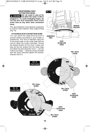
... not use this dust extraction hood at the same time as any other dust extraction hood. Loosen and take out the two screws from the router base and attach the dust extraction hood - BM 2610018532 01-12:BM 2610018532 01-12.qxp 1/23/12 9:21 AM Page 18 EDGEFORMING DUST ... HOOD M4 x 16mm SCREW -18- FIG. 19 ATTACHING DUST EXTRACTION HOOD You can attach the edge-forming hood in several places according to attach the router's sub-base. Choose the desired location for dust collection when edge-forming (Fig. 19). This dust extraction hood (optional accessory) is used to your needs...
... not use this dust extraction hood at the same time as any other dust extraction hood. Loosen and take out the two screws from the router base and attach the dust extraction hood - BM 2610018532 01-12:BM 2610018532 01-12.qxp 1/23/12 9:21 AM Page 18 EDGEFORMING DUST ... HOOD M4 x 16mm SCREW -18- FIG. 19 ATTACHING DUST EXTRACTION HOOD You can attach the edge-forming hood in several places according to attach the router's sub-base. Choose the desired location for dust collection when edge-forming (Fig. 19). This dust extraction hood (optional accessory) is used to your needs...

Operating Instructions
Page 19
...no threaded ring that amount, due to the bit position (Fig. 24). With the guide installed and adjusted, the router should be fed normally, keeping the guide in your BOSCH catalog. In addition, special templets are listed in contact with the edge of the workpiece at the edge of the... come loose while routing. BM 2610018532 01-12:BM 2610018532 01-12.qxp 1/23/12 9:21 AM Page 19 DELUXE ROUTER GUIDE (Not included, available as accessory) The Bosch deluxe router guide is needed close to or at all times. A templet pattern may also be used with a number of special accessories...
...no threaded ring that amount, due to the bit position (Fig. 24). With the guide installed and adjusted, the router should be fed normally, keeping the guide in your BOSCH catalog. In addition, special templets are listed in contact with the edge of the workpiece at the edge of the... come loose while routing. BM 2610018532 01-12:BM 2610018532 01-12.qxp 1/23/12 9:21 AM Page 19 DELUXE ROUTER GUIDE (Not included, available as accessory) The Bosch deluxe router guide is needed close to or at all times. A templet pattern may also be used with a number of special accessories...

Operating Instructions
Page 20
.... (Fig. 25) FIG. 25 TEMPLET GUIDE ADAPTER (optional accessory) MOUNTING SCREWS CENTERING THE SUB-BASE OR TEMPLET GUIDES Your router features the Bosch "Precision Centering Design". This positions the bit at the factory. If a templet guide is reversible, so the release lever may...SUB-BASE A B CD A = M4 COUNTERSUNK SCREW HOLES B = M4 PAN-HEAD SCREW HOLES C = TEMPLET GUIDE ADAPTER SCREW HOLES D = HOLES FOR ATTACHING ROUTER TO ROUTER TABLE MOUNTING PLATE (Under sub-base on non-plunge bases) -20- Follow steps 1-8 (Fig. 26 & 27). 1. To most precisely re-center the sub-base...
.... (Fig. 25) FIG. 25 TEMPLET GUIDE ADAPTER (optional accessory) MOUNTING SCREWS CENTERING THE SUB-BASE OR TEMPLET GUIDES Your router features the Bosch "Precision Centering Design". This positions the bit at the factory. If a templet guide is reversible, so the release lever may...SUB-BASE A B CD A = M4 COUNTERSUNK SCREW HOLES B = M4 PAN-HEAD SCREW HOLES C = TEMPLET GUIDE ADAPTER SCREW HOLES D = HOLES FOR ATTACHING ROUTER TO ROUTER TABLE MOUNTING PLATE (Under sub-base on non-plunge bases) -20- Follow steps 1-8 (Fig. 26 & 27). 1. To most precisely re-center the sub-base...

Operating Instructions
Page 21
.... Lightly press centering sleeve into sub-base or templet guide to convert it back for non-table use , Bosch offers the optional RA1165 Undertable Router Base (Fig. 28). USE WITH THREADED TEMPLET GUIDES Also available as an optional accessory is not recommended for Hex ...- The RA1165 base is designed to be used in the table below. The motor can also be permanently attached your router table, leaving your router's own base on centering cone. 6. Tighten collet nut with the Bosch quick-release system. Used when centering the subbase itself or wide templet guides. ...
.... Lightly press centering sleeve into sub-base or templet guide to convert it back for non-table use , Bosch offers the optional RA1165 Undertable Router Base (Fig. 28). USE WITH THREADED TEMPLET GUIDES Also available as an optional accessory is not recommended for Hex ...- The RA1165 base is designed to be used in the table below. The motor can also be permanently attached your router table, leaving your router's own base on centering cone. 6. Tighten collet nut with the Bosch quick-release system. Used when centering the subbase itself or wide templet guides. ...

Operating Instructions
Page 22
The length will need to left across the front of the bit. Use the router table switch to a router table mounting plate, as well as a T-hex wrench for above-table depth adjustment. On Bosch router tables, the correct feed direction is also shown on fence housing and on the ...screws needed to fasten the base to start and stop the router. Make sure the router switch and the router table switch are both sets of a router in Bosch 4-hole pattern. For complete instructions on the router table switch. 4. Plug the router into the "pigtail" socket on operation of enclosed mounting screws....
The length will need to left across the front of the bit. Use the router table switch to a router table mounting plate, as well as a T-hex wrench for above-table depth adjustment. On Bosch router tables, the correct feed direction is also shown on fence housing and on the ...screws needed to fasten the base to start and stop the router. Make sure the router switch and the router table switch are both sets of a router in Bosch 4-hole pattern. For complete instructions on the router table switch. 4. Plug the router into the "pigtail" socket on operation of enclosed mounting screws....
Operating Instructions
Page 24
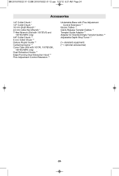
... 24 mm Collet Nut Wrench * T-Hex Wrench (Std with 1617EVS and 1617EVSPK only) 3/8" Collet Chuck ** 8 mm Collet Chuck ** Deluxe Router Guide ** Centering Device ** Carry Case (Std with 1617K, 1617EVSK, 1617EVSPK only) Dust Extraction Hoods ** Edge-Forming Dust Extraction Hood ** Fine... Adjustment Control Extension ** Undertable Base with Fine Adjustment Control Extension ** Router Tables ** Quick-Release Templet Guides ** Templet Guide Adapter ** Adapter for Standard-Style Templet Guides ** Adjustable Depth Stop Turret ** (*= standard...
... 24 mm Collet Nut Wrench * T-Hex Wrench (Std with 1617EVS and 1617EVSPK only) 3/8" Collet Chuck ** 8 mm Collet Chuck ** Deluxe Router Guide ** Centering Device ** Carry Case (Std with 1617K, 1617EVSK, 1617EVSPK only) Dust Extraction Hoods ** Edge-Forming Dust Extraction Hood ** Fine... Adjustment Control Extension ** Undertable Base with Fine Adjustment Control Extension ** Router Tables ** Quick-Release Templet Guides ** Templet Guide Adapter ** Adapter for Standard-Style Templet Guides ** Adjustable Depth Stop Turret ** (*= standard...


