Update Manual
Page 3
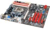
.... 4. For better performance, the software is completed. The information and pictures described above about the software are subject to restart the system. The BIOSTAR BIOS Flasher is completed, asking you are for your BIOS via USB pen drive. 1. To enter the utility, press during the POST process. ...5. Select the proper BIOS file, and a message asking if you to be slightly different from this manual. A dialog pops out after BIOS flash is built in the BIOS ROM. All the information and content above are sure to search for the ...
.... 4. For better performance, the software is completed. The information and pictures described above about the software are subject to restart the system. The BIOSTAR BIOS Flasher is completed, asking you are for your BIOS via USB pen drive. 1. To enter the utility, press during the POST process. ...5. Select the proper BIOS file, and a message asking if you to be slightly different from this manual. A dialog pops out after BIOS flash is built in the BIOS ROM. All the information and content above are sure to search for the ...

Setup Manual
Page 1
... with the limits of a Class B digital device, pursuant to Part 15 of the FCC Rules. Duplication of conformity We declare this user's manual. The vendor makes no guarantee that interference will not be applied Dichiarazione di conformità sintetica Ai sensi dell'art. 2 comma 3 del ...beforehand. The content of their respective companies. All the brand and product names are designed to notify any purpose. TZ77XE3/TZ75XE3 Setup Manual FCC Information and Copyright This equipment has been tested and found in this product is not allowed without first obtaining the vendor's approval...
... with the limits of a Class B digital device, pursuant to Part 15 of the FCC Rules. Duplication of conformity We declare this user's manual. The vendor makes no guarantee that interference will not be applied Dichiarazione di conformità sintetica Ai sensi dell'art. 2 comma 3 del ...beforehand. The content of their respective companies. All the brand and product names are designed to notify any purpose. TZ77XE3/TZ75XE3 Setup Manual FCC Information and Copyright This equipment has been tested and found in this product is not allowed without first obtaining the vendor's approval...

Setup Manual
Page 3
... a dry and stable working environment with sufficient lighting. „ Always disconnect the computer from power outlet before operation. „ Before you for ATX Case X 1 User's Manual X 1 Fully Setup Driver DVD X 1 SLI Bridge X 1 CFX Bridge X 1 Note: The package contents may damage the equipment. „ Keep the computer from anti-static bag, ground...
... a dry and stable working environment with sufficient lighting. „ Always disconnect the computer from power outlet before operation. „ Before you for ATX Case X 1 User's Manual X 1 Fully Setup Driver DVD X 1 SLI Bridge X 1 CFX Bridge X 1 Note: The package contents may damage the equipment. „ Keep the computer from anti-static bag, ground...

Setup Manual
Page 4
Motherboard Manual 1.3 MOTHERBOARD FEATURES SPEC Supports Execute Disable Bit / Enhanced Intel Socket 1155 SpeedStep® / Intel Architecture-64 / Extended CPU Intel Core i7 / i5 / i3 / Pentium / Celeron ...
Motherboard Manual 1.3 MOTHERBOARD FEATURES SPEC Supports Execute Disable Bit / Enhanced Intel Socket 1155 SpeedStep® / Intel Architecture-64 / Extended CPU Intel Core i7 / i5 / i3 / Pentium / Celeron ...

Setup Manual
Page 6
Motherboard Manual 1.4 REAR PANEL CONNECTORS PS /2 Ke yb oard VGA LA N USB2.0X2 HDMI DV I- D USB3.0X2 USB2.0X2 Cen ter Rear Side Line In Line Ou t ...
Motherboard Manual 1.4 REAR PANEL CONNECTORS PS /2 Ke yb oard VGA LA N USB2.0X2 HDMI DV I- D USB3.0X2 USB2.0X2 Cen ter Rear Side Line In Line Ou t ...

Setup Manual
Page 8
Please refer below instruction to ensure pin legs won't be damaged. 2. Remove Pin Cap before installation, and make good preservation for future use. Step 1: Pull the socket locking lever out from the socket and then raise the lever up. Motherboard Manual CHAPTER 2: HARDWARE INSTALLATION 2.1 INSTALLING CENTRAL PROCESSING UNIT (CPU) Notice: 1. When the CPU is removed, cover the Pin Cap on the empty socket to remove the pin cap. Step 2: Remove the Pin Cap. 6 The motherboard might equip with two different types of pin cap.
Please refer below instruction to ensure pin legs won't be damaged. 2. Remove Pin Cap before installation, and make good preservation for future use. Step 1: Pull the socket locking lever out from the socket and then raise the lever up. Motherboard Manual CHAPTER 2: HARDWARE INSTALLATION 2.1 INSTALLING CENTRAL PROCESSING UNIT (CPU) Notice: 1. When the CPU is removed, cover the Pin Cap on the empty socket to remove the pin cap. Step 2: Remove the Pin Cap. 6 The motherboard might equip with two different types of pin cap.

Setup Manual
Page 10
... is the positive and should be connected to pin#2, and the black wire is Ground and should be different according to the fan manufacturer. Motherboard Manual 2.2 FAN HEADERS These fan headers support cooling-fans built in the computer. Connect the fan cable to the connector while matching the black wire to...
... is the positive and should be connected to pin#2, and the black wire is Ground and should be different according to the fan manufacturer. Motherboard Manual 2.2 FAN HEADERS These fan headers support cooling-fans built in the computer. Connect the fan cable to the connector while matching the black wire to...

Setup Manual
Page 12
... X O X O Enabled O O O O Enabled O X X O Enabled X O O X (O means memory installed, X means memory not installed.) The DRAM bus width of the same density in pairs, shown in the table. Motherboard Manual B.
... X O X O Enabled O O O O Enabled O X X O Enabled X O O X (O means memory installed, X means memory not installed.) The DRAM bus width of the same density in pairs, shown in the table. Motherboard Manual B.

Setup Manual
Page 14
the speed of PEX16_2 is enabled; PCI-Express 2.0 compliant. - PEX16_1 PEX1_1 PEX1_2 PEX16_2 PEX16_3 12 Motherboard Manual PEX16_1/ PEX16_2: PCI-Express Gen3 x16 (x16 / x8) (Nvidia SLI and AMD CrossFireX) Slots - Maximum theoretical realized bandwidth of 16GB/s simultaneously per direction, for an ...
the speed of PEX16_2 is enabled; PCI-Express 2.0 compliant. - PEX16_1 PEX1_1 PEX1_2 PEX16_2 PEX16_3 12 Motherboard Manual PEX16_1/ PEX16_2: PCI-Express Gen3 x16 (x16 / x8) (Nvidia SLI and AMD CrossFireX) Slots - Maximum theoretical realized bandwidth of 16GB/s simultaneously per direction, for an ...

Setup Manual
Page 16
Motherboard Manual ATXPWR1: ATX Power Source Connector This connector allows user to connect 24-pin power connector on the ATX power supply. 12 24 1 13 Pin Assignment Pin Assignment 13 +3.3V 14 -12V 15 Ground 16 PS_ON 17 Ground 18 Ground 19 Ground 20 NC 21 +5V 22 +5V 23 +5V 24 Ground 1 +3.3V 2 +3.3V 3 Ground 4 +5V 5 Ground 6 +5V 7 Ground 8 PW_OK 9 Standby Voltage+5V 10 +12V 11 +12V 12 +3.3V Note: Before you power on the system, please make sure that ATXPWR1 and ATXPWR2 connectors have been well plugged-in. 14
Motherboard Manual ATXPWR1: ATX Power Source Connector This connector allows user to connect 24-pin power connector on the ATX power supply. 12 24 1 13 Pin Assignment Pin Assignment 13 +3.3V 14 -12V 15 Ground 16 PS_ON 17 Ground 18 Ground 19 Ground 20 NC 21 +5V 22 +5V 23 +5V 24 Ground 1 +3.3V 2 +3.3V 3 Ground 4 +5V 5 Ground 6 +5V 7 Ground 8 PW_OK 9 Standby Voltage+5V 10 +12V 11 +12V 12 +3.3V Note: Before you power on the system, please make sure that ATXPWR1 and ATXPWR2 connectors have been well plugged-in. 14

Setup Manual
Page 18
...- 13 Ground 14 SSTX2+ 15 SSTX2- 16 Ground 17 SSRX2+ 18 SSRX2- 19 VBUS1 20 Key NOTE: USB3.0 is only supported by Windows 7. 16 Motherboard Manual F_USB1/F_USB2: Headers for USB 3.0 Ports at Front Panel These headers allow user to connect additional USB cable on the PC front panel, and also...
...- 13 Ground 14 SSTX2+ 15 SSTX2- 16 Ground 17 SSRX2+ 18 SSRX2- 19 VBUS1 20 Key NOTE: USB3.0 is only supported by Windows 7. 16 Motherboard Manual F_USB1/F_USB2: Headers for USB 3.0 Ports at Front Panel These headers allow user to connect additional USB cable on the PC front panel, and also...

Setup Manual
Page 20
... data. J_COM1: Serial Port Connector The motherboard has a Serial Port Connector for five seconds. 4. Remove AC power line. 2. Set the jumper to "Pin 2-3 close ". 5. Motherboard Manual JCMOS1: Clear CMOS Header Placing the jumper on the AC. 6. Please carefully follow the procedures to restore the BIOS safe setting and the CMOS data...
... data. J_COM1: Serial Port Connector The motherboard has a Serial Port Connector for five seconds. 4. Remove AC power line. 2. Set the jumper to "Pin 2-3 close ". 5. Motherboard Manual JCMOS1: Clear CMOS Header Placing the jumper on the AC. 6. Please carefully follow the procedures to restore the BIOS safe setting and the CMOS data...
Setup Manual
Page 22
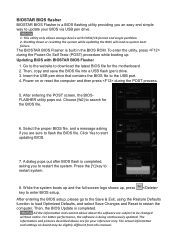
Motherboard Manual CHAPTER 4: RAID / AHCI FUNCTIONS 4.1 OPERATING SYSTEM CHIP Intel Z77 / Z75 SATA1/SATA2/ SATA3/SATA4/ SATA5/SATA6 Intel Z77 / Z75 SATA1/SATA2/ SATA3/SATA4/ SATA5/SATA6 ...
Motherboard Manual CHAPTER 4: RAID / AHCI FUNCTIONS 4.1 OPERATING SYSTEM CHIP Intel Z77 / Z75 SATA1/SATA2/ SATA3/SATA4/ SATA5/SATA6 Intel Z77 / Z75 SATA1/SATA2/ SATA3/SATA4/ SATA5/SATA6 ...

Setup Manual
Page 24
If any fault tolerance. Block 1 Block 3 Block 5 Block 2 Block 4 Block 6 22 Motherboard Manual 4.3 HOW RAID WORKS RAID 0: The controller "stripes" data across multiple drives in a RAID 0 array system. Features and Benefits Drives: Minimum 2, and maximum is lost. &#...
If any fault tolerance. Block 1 Block 3 Block 5 Block 2 Block 4 Block 6 22 Motherboard Manual 4.3 HOW RAID WORKS RAID 0: The controller "stripes" data across multiple drives in a RAID 0 array system. Features and Benefits Drives: Minimum 2, and maximum is lost. &#...

Setup Manual
Page 25
... the active volume or drive is corrupted or becomes unavailable because of one drive fail, the controller switches to the other application that eliminates tedious manual backups to more expensive and less reliable media. TZ77XE3/TZ75XE3 RAID 1: Every read and write is actually carried out in parallel across 2 disk drives in...
... the active volume or drive is corrupted or becomes unavailable because of one drive fail, the controller switches to the other application that eliminates tedious manual backups to more expensive and less reliable media. TZ77XE3/TZ75XE3 RAID 1: Every read and write is actually carried out in parallel across 2 disk drives in...

Setup Manual
Page 26
... maximum is 6 or 8, depending on the platform. Benefits: Optimizes for both fault tolerance and performance, allowing for improved resiliency, performance and rebuild performance. Motherboard Manual RAID 10: RAID 1 drives can be simultaneously used with other RAID levels in a RAID 10 solution for automatic redundancy. May be stripped using RAID 0 techniques.
... maximum is 6 or 8, depending on the platform. Benefits: Optimizes for both fault tolerance and performance, allowing for improved resiliency, performance and rebuild performance. Motherboard Manual RAID 10: RAID 1 drives can be simultaneously used with other RAID levels in a RAID 10 solution for automatic redundancy. May be stripped using RAID 0 techniques.

Setup Manual
Page 28
... BIOS, and install operating system. 3. Select "Accelerate" page, and make sure the status of RAID with an Intel SSD drive can be improved better. Motherboard Manual 4.4 INTEL SMART RESPONSE TECHNOLOGY With Intel(R) Smart Response Technology, the performance of accelerated device has been enabled accelerated. 26 Installing Smart Response Technology 1. Install RAID...
... BIOS, and install operating system. 3. Select "Accelerate" page, and make sure the status of RAID with an Intel SSD drive can be improved better. Motherboard Manual 4.4 INTEL SMART RESPONSE TECHNOLOGY With Intel(R) Smart Response Technology, the performance of accelerated device has been enabled accelerated. 26 Installing Smart Response Technology 1. Install RAID...

Setup Manual
Page 29
... Navigator Engine (O.N.E.) O.N.E provides 4 systems allowing users to the UEFI BIOS Manual in this manual. Notice: Not all types of setting up the UEFI BIOS, please refer to customize personal overclock settings: Manual CPU System, Manual Memory System, Manual PWM System, and Manual Voltage System. WARNING !! The UEFI BIOS information described below in the Setup...T-SERIES UEFI BIOS T-Series UEFI BIOS Features Overclocking Navigator Engine (O.N.E.) Self Recovery System (S.R.S) Smart Fan Function BIO-Flasher: Update UEFI BIOS file from this manual is being continuously updated.
... Navigator Engine (O.N.E.) O.N.E provides 4 systems allowing users to the UEFI BIOS Manual in this manual. Notice: Not all types of setting up the UEFI BIOS, please refer to customize personal overclock settings: Manual CPU System, Manual Memory System, Manual PWM System, and Manual Voltage System. WARNING !! The UEFI BIOS information described below in the Setup...T-SERIES UEFI BIOS T-Series UEFI BIOS Features Overclocking Navigator Engine (O.N.E.) Self Recovery System (S.R.S) Smart Fan Function BIO-Flasher: Update UEFI BIOS file from this manual is being continuously updated.

Setup Manual
Page 30
..., we will automatically log in "Advanced Menu". Self Recovery System (S.R.S.) This function can prevent system hang-up due to control CPU/System Temperature vs. Motherboard Manual NOTE Overclock is controlled automatically by overclocking. When the system hangs up . will not be responsible for inexperienced users. This function will be re-configured...
..., we will automatically log in "Advanced Menu". Self Recovery System (S.R.S.) This function can prevent system hang-up due to control CPU/System Temperature vs. Motherboard Manual NOTE Overclock is controlled automatically by overclocking. When the system hangs up . will not be responsible for inexperienced users. This function will be re-configured...

Setup Manual
Page 32
The driver installation program would appear if the Auto-run function has been enabled. 7. Motherboard Manual 5.2 T-SERIES SOFTWARE Installing T-Series Software 6. Follow the on CPU and Memory. TOverclocker TOverclocker presents a simple Windows-based system performance enhancement and manageability utility. This utility ...
The driver installation program would appear if the Auto-run function has been enabled. 7. Motherboard Manual 5.2 T-SERIES SOFTWARE Installing T-Series Software 6. Follow the on CPU and Memory. TOverclocker TOverclocker presents a simple Windows-based system performance enhancement and manageability utility. This utility ...

