
Setup Manual
Page 1
TZ77XE3/TZ75XE3 Setup Manual FCC Information and Copyright This equipment has been tested and found in this user's manual. The vendor makes no guarantee that interference ...
TZ77XE3/TZ75XE3 Setup Manual FCC Information and Copyright This equipment has been tested and found in this user's manual. The vendor makes no guarantee that interference ...

Setup Manual
Page 3
... equipment. „ Keep the computer from anti-static bag, ground yourself properly by touching any unfastened small parts inside the case after installation. CHAPTER 1: INTRODUCTION TZ77XE3/TZ75XE3 1.1 BEFORE YOU START Thank you take the motherboard out from dangerous area, such as heat source, humid air and water. „ The operating temperatures...
... equipment. „ Keep the computer from anti-static bag, ground yourself properly by touching any unfastened small parts inside the case after installation. CHAPTER 1: INTRODUCTION TZ77XE3/TZ75XE3 1.1 BEFORE YOU START Thank you take the motherboard out from dangerous area, such as heat source, humid air and water. „ The operating temperatures...

Setup Manual
Page 4
... / 100 Mb/s / 1Gb/s auto negotiation Half / Full duplex capability Sound Codec ALC892 7.1 channels audio out High Definition Audio USB3.0 Z77 (TZ77XE3) / Z75 (TZ75XE3) Data transfer rates up to 600 MB/s PCI slot x2 Supports PCI expansion cards PCI Express Gen3 x 16 slot Supports ...Extended CPU Intel Core i7 / i5 / i3 / Pentium / Celeron Memory 64 Technology / Virtualization Technology / processor Hyper Threading Chipset Intel Z77 (TZ77XE3) Intel Z75 (TZ75XE3) IT8728 Environment Control initiatives, Super I/O Provides the most commonly used legacy Super I/O functionality.
... / 100 Mb/s / 1Gb/s auto negotiation Half / Full duplex capability Sound Codec ALC892 7.1 channels audio out High Definition Audio USB3.0 Z77 (TZ77XE3) / Z75 (TZ75XE3) Data transfer rates up to 600 MB/s PCI slot x2 Supports PCI expansion cards PCI Express Gen3 x 16 slot Supports ...Extended CPU Intel Core i7 / i5 / i3 / Pentium / Celeron Memory 64 Technology / Virtualization Technology / processor Hyper Threading Chipset Intel Z77 (TZ77XE3) Intel Z75 (TZ75XE3) IT8728 Environment Control initiatives, Super I/O Provides the most commonly used legacy Super I/O functionality.

Setup Manual
Page 5
connection ATX Biostar reserves the right to USB3.0 devices x6 Provide Audio-In/Out and Mic. SATA3 Connector SATA2 Connector Front Panel Connector Front Audio Connector CPU Fan ... Port VGA Port Back Panel DVI Port I/O LAN port USB2.0 Port USB3.0 Port Audio Jack Board Size 244 (W) x 305 (L) mm OS Support Windows XP / Vista / 7 TZ77XE3/TZ75XE3 x2 Each connector supports 1 SATA3 devices x4 Each connector supports 1 SATA2 devices x1 Supports front panel facilities x1 Supports front panel audio function x1...
connection ATX Biostar reserves the right to USB3.0 devices x6 Provide Audio-In/Out and Mic. SATA3 Connector SATA2 Connector Front Panel Connector Front Audio Connector CPU Fan ... Port VGA Port Back Panel DVI Port I/O LAN port USB2.0 Port USB3.0 Port Audio Jack Board Size 244 (W) x 305 (L) mm OS Support Windows XP / Vista / 7 TZ77XE3/TZ75XE3 x2 Each connector supports 1 SATA3 devices x4 Each connector supports 1 SATA2 devices x1 Supports front panel facilities x1 Supports front panel audio function x1...
Setup Manual
Page 7
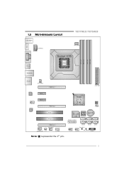
HDMI1 1.5 MOTHERBOARD LAYOUT USB_KBMS1 ATXPWR2 TZ77XE3/TZ75XE3 CPU_FAN1 DDR3_A1 DDR3_A2 DDR3_B1 DDR3_B2 VGA1 DVI1 USB3_0 RJ45USB1 Socket 1155 CP U 1 AUDIO1 SYS_FAN2 PEX16_1 ATXPWR1 LAN PEX1_1 F_ AUDIO1 CODEC PEX1_2 PEX16_2 PCI1 PCI2 PEX16_3 SYS_FAN1 JSPDIFOUT1 CIR1 J _C OM1 Intel Z77/ Z75 BIOS JCMOS 1 Super I/O BAT1 J FR ON T_U SB3_1 F_USB1 SATA6 SATA5 SW_RST1 SATA4 SATA3 SATA2 SATA1 F_USB2 SW_PW R1 PANEL1 Note: ■ represents the 1st pin. 5
HDMI1 1.5 MOTHERBOARD LAYOUT USB_KBMS1 ATXPWR2 TZ77XE3/TZ75XE3 CPU_FAN1 DDR3_A1 DDR3_A2 DDR3_B1 DDR3_B2 VGA1 DVI1 USB3_0 RJ45USB1 Socket 1155 CP U 1 AUDIO1 SYS_FAN2 PEX16_1 ATXPWR1 LAN PEX1_1 F_ AUDIO1 CODEC PEX1_2 PEX16_2 PCI1 PCI2 PEX16_3 SYS_FAN1 JSPDIFOUT1 CIR1 J _C OM1 Intel Z77/ Z75 BIOS JCMOS 1 Super I/O BAT1 J FR ON T_U SB3_1 F_USB1 SATA6 SATA5 SW_RST1 SATA4 SATA3 SATA2 SATA1 F_USB2 SW_PW R1 PANEL1 Note: ■ represents the 1st pin. 5

Setup Manual
Page 9
Align the notches with your thumb and index fingers, oriented as shown. Connect the CPU FAN power cable into the CPU_FAN1 to complete the installation. TZ77XE3/TZ75XE3 Step 3: Hold processor with the socket. Step 4: Hold the CPU down without tilting or sliding the processor in the socket. Step 5: Put the CPU Fan and heatsink assembly on the CPU and buckle it on the retention frame. Lower the processor straight down firmly, and then lower the lever to locked position to complete the installation. 7
Align the notches with your thumb and index fingers, oriented as shown. Connect the CPU FAN power cable into the CPU_FAN1 to complete the installation. TZ77XE3/TZ75XE3 Step 3: Hold processor with the socket. Step 4: Hold the CPU down without tilting or sliding the processor in the socket. Step 5: Put the CPU Fan and heatsink assembly on the CPU and buckle it on the retention frame. Lower the processor straight down firmly, and then lower the lever to locked position to complete the installation. 7

Setup Manual
Page 11
Memory Modules TZ77XE3/TZ75XE3 D DR3_A1 DD R3_A2 DD R3_B1 DD R3_B2 1. Unlock a DIMM slot by pressing the retaining clips outward. Pull it . Insert the DIMM vertically and firmly into the slot until the retaining chip snap back in smoothly, do not force it all the way out and try again. 9 2.3 INSTALLING SYSTEM MEMORY A. Align a DIMM on the slot such that the notch on the DIMM matches the break on the Slot. 2. Note: If the DIMM does not go in place and the DIMM is properly seated.
Memory Modules TZ77XE3/TZ75XE3 D DR3_A1 DD R3_A2 DD R3_B1 DD R3_B2 1. Unlock a DIMM slot by pressing the retaining clips outward. Pull it . Insert the DIMM vertically and firmly into the slot until the retaining chip snap back in smoothly, do not force it all the way out and try again. 9 2.3 INSTALLING SYSTEM MEMORY A. Align a DIMM on the slot such that the notch on the DIMM matches the break on the Slot. 2. Note: If the DIMM does not go in place and the DIMM is properly seated.

Setup Manual
Page 13
2.4 CONNECTORS AND SLOTS TZ77XE3/TZ75XE3 SATA1/SATA2: Serial ATA3.0 Connectors The motherboard has a PCI to SATA Controller with 4 channels SATA2 interface, it satisfies the SATA 3.0 spec and with transfer rate of 6.0Gb/s. S ATA 2 S ATA 1 7 41 Pin Assignment 1 Ground 2 TX+ 3 TX4 Ground 5 RX6 RX+ 7 Ground SATA3 ~ 6: Serial ATA2.0 Connectors The motherboard has a PCI to SATA Controller with 2 channels SATA interface, it satisfies the SATA 2.0 spec and with transfer rate of 3.0Gb/s. SATA6 SATA4 SATA5 SATA3 7 41 Pin Assignment 1 Ground 2 TX+ 3 TX4 Ground 5 RX6 RX+ 7 Ground 11
2.4 CONNECTORS AND SLOTS TZ77XE3/TZ75XE3 SATA1/SATA2: Serial ATA3.0 Connectors The motherboard has a PCI to SATA Controller with 4 channels SATA2 interface, it satisfies the SATA 3.0 spec and with transfer rate of 6.0Gb/s. S ATA 2 S ATA 1 7 41 Pin Assignment 1 Ground 2 TX+ 3 TX4 Ground 5 RX6 RX+ 7 Ground SATA3 ~ 6: Serial ATA2.0 Connectors The motherboard has a PCI to SATA Controller with 2 channels SATA interface, it satisfies the SATA 2.0 spec and with transfer rate of 3.0Gb/s. SATA6 SATA4 SATA5 SATA3 7 41 Pin Assignment 1 Ground 2 TX+ 3 TX4 Ground 5 RX6 RX+ 7 Ground 11

Setup Manual
Page 15
If the CPU power plug is 4-pin, please plug it is a bus standard for expansion cards. PCI stands for Peripheral Component Interconnect, and it into Pin 1-2-5-6 of ATXPWR2. 8 4 Pin Assignment 1 +12V 2 +12V 5 13 +12V 4 +12V 5 Ground 6 Ground 7 Ground 8 Ground 13 TZ77XE3/TZ75XE3 PCI1/PCI2: Peripheral Component Interconnect Slots This motherboard is designated as 32 bits. This PCI slot is equipped with 2 standard PCI slots. PCI 1 PCI2 ATXPWR2: ATX Power Source Connectors These connectors provide +12V to CPU power circuit.
If the CPU power plug is 4-pin, please plug it is a bus standard for expansion cards. PCI stands for Peripheral Component Interconnect, and it into Pin 1-2-5-6 of ATXPWR2. 8 4 Pin Assignment 1 +12V 2 +12V 5 13 +12V 4 +12V 5 Ground 6 Ground 7 Ground 8 Ground 13 TZ77XE3/TZ75XE3 PCI1/PCI2: Peripheral Component Interconnect Slots This motherboard is designated as 32 bits. This PCI slot is equipped with 2 standard PCI slots. PCI 1 PCI2 ATXPWR2: ATX Power Source Connectors These connectors provide +12V to CPU power circuit.

Setup Manual
Page 17
... 15 When the jumper cap is placed on pins, the jumper is "close", if not, that means the jumper is "open". POW_LED On/Off ++ - 9 16 1 8 +- TZ77XE3/TZ75XE3 CHAPTER 3: HEADERS & JUMPERS SETUP 3.1 HOW TO SETUP JUMPERS The illustration shows how to connect the PC case's front panel switch functions.
... 15 When the jumper cap is placed on pins, the jumper is "close", if not, that means the jumper is "open". POW_LED On/Off ++ - 9 16 1 8 +- TZ77XE3/TZ75XE3 CHAPTER 3: HEADERS & JUMPERS SETUP 3.1 HOW TO SETUP JUMPERS The illustration shows how to connect the PC case's front panel switch functions.

Setup Manual
Page 19
... This header is for infrared remote control and communication. 26 15 Pin Assignment 1 IrDA serial input 2 Ground 3 Ground 4 Key 5 IrDA serial output 6 IR Power 17 TZ77XE3/TZ75XE3 F_AUDIO1: Front Panel Audio Header This header allows user to connect the PCI bracket SPDIF output header. This header supports HD and AC'97...
... This header is for infrared remote control and communication. 26 15 Pin Assignment 1 IrDA serial input 2 Ground 3 Ground 4 Key 5 IrDA serial output 6 IR Power 17 TZ77XE3/TZ75XE3 F_AUDIO1: Front Panel Audio Header This header allows user to connect the PCI bracket SPDIF output header. This header supports HD and AC'97...

Setup Manual
Page 21
SW_PWR1 SW_RST1 19 After the booting sequence, it will show current CPU temperature through hexadecimal figure. TZ77XE3/TZ75XE3 BIOS POST Code/CPU Temperature Indicator This indicator will show POST code while booting. SW_RST1: Reset button. On-Board Buttons There are 2 on-board buttons. Please refer to Chapter 6.3 for all the BIOS POST codes. SW_PWR1: Power Switch button.
SW_PWR1 SW_RST1 19 After the booting sequence, it will show current CPU temperature through hexadecimal figure. TZ77XE3/TZ75XE3 BIOS POST Code/CPU Temperature Indicator This indicator will show POST code while booting. SW_RST1: Reset button. On-Board Buttons There are 2 on-board buttons. Please refer to Chapter 6.3 for all the BIOS POST codes. SW_PWR1: Power Switch button.
Setup Manual
Page 23
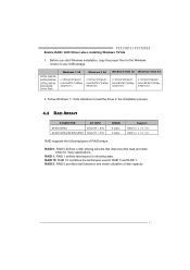
... 5 provides fault tolerance and better utilization of RAID arrays: RAID 0: RAID 0 defines a disk striping scheme that improves disk read and write times for mirroring data. TZ77XE3/TZ75XE3 Enable RAID / AHCI Driver when installing Windows 7/Vista 1. Support RAID 0 / 1 / 5 / 10 RAID 0 / 1 / 5 / 10 RAID supports the following types of disk capacity. 21 RAID 1: RAID...
... 5 provides fault tolerance and better utilization of RAID arrays: RAID 0: RAID 0 defines a disk striping scheme that improves disk read and write times for mirroring data. TZ77XE3/TZ75XE3 Enable RAID / AHCI Driver when installing Windows 7/Vista 1. Support RAID 0 / 1 / 5 / 10 RAID 0 / 1 / 5 / 10 RAID supports the following types of disk capacity. 21 RAID 1: RAID...

Setup Manual
Page 25
... media. RAID techniques can reside on the same disk or on a second redundant drive in a RAID 1 array system. Block 1 Block 2 Block 3 Block 1 Block 2 Block 3 23 TZ77XE3/TZ75XE3 RAID 1: Every read and write is actually carried out in parallel across 2 disk drives in the array. Performance is impaired during drive rebuilds. ...
... media. RAID techniques can reside on the same disk or on a second redundant drive in a RAID 1 array system. Block 1 Block 2 Block 3 Block 1 Block 2 Block 3 23 TZ77XE3/TZ75XE3 RAID 1: Every read and write is actually carried out in parallel across 2 disk drives in the array. Performance is impaired during drive rebuilds. ...

Setup Manual
Page 27
TZ77XE3/TZ75XE3 RAID 5: RAID 5 stripes both data and parity information across all the drives in the array. Features and Benefits Drives: Minimum 3. Uses: RAID 5 ...
TZ77XE3/TZ75XE3 RAID 5: RAID 5 stripes both data and parity information across all the drives in the array. Features and Benefits Drives: Minimum 3. Uses: RAID 5 ...

Setup Manual
Page 28
... Intel(R) Smart Response Technology Driver). Double click it to the optical drive, and Install all processes finish, reboot the system. 4. This function is only for TZ77XE3. Select "Accelerate" page, and make sure the status of RAID with an Intel SSD drive can be improved better. Install RAID drives (RAID 0, 1, 5) and an...
... Intel(R) Smart Response Technology Driver). Double click it to the optical drive, and Install all processes finish, reboot the system. 4. This function is only for TZ77XE3. Select "Accelerate" page, and make sure the status of RAID with an Intel SSD drive can be improved better. Install RAID drives (RAID 0, 1, 5) and an...

Setup Manual
Page 29
... USB Flash Drive !! A. WARNING !! The UEFI BIOS information described below in the Setup DVD. For further information of Intel CPU perform above overclock setting ideally; TZ77XE3/TZ75XE3 CHAPTER 5: T-SERIES UEFI BIOS & SOFTWARE 5.1 T-SERIES UEFI BIOS T-Series UEFI BIOS Features Overclocking Navigator Engine (O.N.E.) Self Recovery System (S.R.S) Smart Fan Function BIO-Flasher: Update...
... USB Flash Drive !! A. WARNING !! The UEFI BIOS information described below in the Setup DVD. For further information of Intel CPU perform above overclock setting ideally; TZ77XE3/TZ75XE3 CHAPTER 5: T-SERIES UEFI BIOS & SOFTWARE 5.1 T-SERIES UEFI BIOS T-Series UEFI BIOS Features Overclocking Navigator Engine (O.N.E.) Self Recovery System (S.R.S) Smart Fan Function BIO-Flasher: Update...

Setup Manual
Page 31
... CPU fan will turn on. Fan Ctrl Start Value This item sets CPU FAN Start Speed Value. Fan Ctrl On(℃) When CPU temperature is . TZ77XE3/TZ75XE3 CPU Smart FAN This item allows you to calibrate CPU FAN.
... CPU fan will turn on. Fan Ctrl Start Value This item sets CPU FAN Start Speed Value. Fan Ctrl On(℃) When CPU temperature is . TZ77XE3/TZ75XE3 CPU Smart FAN This item allows you to calibrate CPU FAN.

Setup Manual
Page 33
It also provides six pre-set modes for you to see its information. The Memory tab provides information on the CPU and motherboard. The OC Tweaker tab allows you : 31 You can select memory module on a specific slot to change system clock settings and voltages settings. TZ77XE3/TZ75XE3 The CPU tab provides information on the memory module(s).
It also provides six pre-set modes for you to see its information. The Memory tab provides information on the CPU and motherboard. The OC Tweaker tab allows you : 31 You can select memory module on a specific slot to change system clock settings and voltages settings. TZ77XE3/TZ75XE3 The CPU tab provides information on the memory module(s).

Setup Manual
Page 35
... and best power efficiency on light loading; TZ77XE3/TZ75XE3 Pressing TOVERCLOCKER logo displays information about manufacturer and software version. You can update current version by disabling extra phases while CPU is on your CPU Usage, CPU Watt, and CPU Temperature. Green Power II Utility BIOSTAR G.P.U II (Green Power Utility) is for reference...
... and best power efficiency on light loading; TZ77XE3/TZ75XE3 Pressing TOVERCLOCKER logo displays information about manufacturer and software version. You can update current version by disabling extra phases while CPU is on your CPU Usage, CPU Watt, and CPU Temperature. Green Power II Utility BIOSTAR G.P.U II (Green Power Utility) is for reference...