Setup Manual
Page 2
... 1: Introduction 1 1.1 Before You Start 1 1.2 Package Checklist 1 1.3 Motherboard Features 2 1.4 Rear Panel Connectors 3 1.5 Motherboard Layout 3 Chapter 2: Hardware Installation 5 2.1 Installing Central Processing Unit (CPU 5 2.2 FAN Headers 7 2.3 Installing System Memory 8 2.4 Connectors and Slots 10 Chapter 3: Headers & Jumpers Setup 13 3.1 How to Setup Jumpers 13 3.2 Detail Settings 13 Chapter 4: Useful Help 17 4.1 Driver Installation Note 17...
... 1: Introduction 1 1.1 Before You Start 1 1.2 Package Checklist 1 1.3 Motherboard Features 2 1.4 Rear Panel Connectors 3 1.5 Motherboard Layout 3 Chapter 2: Hardware Installation 5 2.1 Installing Central Processing Unit (CPU 5 2.2 FAN Headers 7 2.3 Installing System Memory 8 2.4 Connectors and Slots 10 Chapter 3: Headers & Jumpers Setup 13 3.1 How to Setup Jumpers 13 3.2 Detail Settings 13 Chapter 4: Useful Help 17 4.1 Driver Installation Note 17...
Setup Manual
Page 4
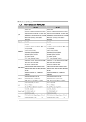
... Mode DDR3 memory module Dual Channel Mode DDR3 memory module Main Memory Supports DDR3 1066/1333/1600 (depending Supports DDR3 1066/1333/1600 (depending on CPU) on CPU) x1 PCI Express Gen2 x1 Slot x2 2 Super I /O functionality. SATA Version 2.0 specification compliant Data transfer rates up to 3.0 Gb/s. Motherboard Manual 1.3 MOTHERBOARD FEATURES H61MGC H61MLC Socket...
... Mode DDR3 memory module Dual Channel Mode DDR3 memory module Main Memory Supports DDR3 1066/1333/1600 (depending Supports DDR3 1066/1333/1600 (depending on CPU) on CPU) x1 PCI Express Gen2 x1 Slot x2 2 Super I /O functionality. SATA Version 2.0 specification compliant Data transfer rates up to 3.0 Gb/s. Motherboard Manual 1.3 MOTHERBOARD FEATURES H61MGC H61MLC Socket...

Setup Manual
Page 10
D DR3_A1 DD R3_B1 Motherboard Manual 2.3 INSTALLING SYSTEM MEMORY A. Memory Modules 1. Align a DIMM on the slot such that the notch on the DIMM matches the break on the Slot. 8 Unlock a DIMM slot by pressing the retaining clips outward.
D DR3_A1 DD R3_B1 Motherboard Manual 2.3 INSTALLING SYSTEM MEMORY A. Memory Modules 1. Align a DIMM on the slot such that the notch on the DIMM matches the break on the Slot. 8 Unlock a DIMM slot by pressing the retaining clips outward.

Setup Manual
Page 11
... Location DDR3_A1 DDR3_B1 DDR3 Module 512MB/1GB/2GB/4GB/8GB 512MB/1GB/2GB/4GB/8GB Total Memory Size Max is properly seated. Dual Channel Status DDR3_A1 DDR3_B1 Disabled O X Disabled X O Enabled O O (O means memory installed; Note: If the DIMM does not go in the table. B. Pull it .... C. X, not installed.) The DRAM bus width of the same density in pairs, shown in smoothly, do not force it all the way out and try again. H61MGC / H61MLC 2.
... Location DDR3_A1 DDR3_B1 DDR3 Module 512MB/1GB/2GB/4GB/8GB 512MB/1GB/2GB/4GB/8GB Total Memory Size Max is properly seated. Dual Channel Status DDR3_A1 DDR3_B1 Disabled O X Disabled X O Enabled O O (O means memory installed; Note: If the DIMM does not go in the table. B. Pull it .... C. X, not installed.) The DRAM bus width of the same density in pairs, shown in smoothly, do not force it all the way out and try again. H61MGC / H61MLC 2.

Setup Manual
Page 25
...good modules. z If beep codes are generated when all other expansion 6, 7 cards are absent, consult your system manufacturer. 4.4 AMI BIOS BEEP CODE H61MGC / H61MLC Boot Block Beep Codes Number of Beeps Description 1 No media present. (Insert diskette in floppy drive A:) 2 "AMIBOOT.ROM" file not found...cards back into the system one of the add-in flash device) POST BIOS Beep Codes Number of Beeps Description 1 Memory refresh timer error 3 Base memory read error 7 No Flash EPROM detected 10 Flash Erase error 11 Flash Program error 12 "AMIBOOT.ROM" file size error...
...good modules. z If beep codes are generated when all other expansion 6, 7 cards are absent, consult your system manufacturer. 4.4 AMI BIOS BEEP CODE H61MGC / H61MLC Boot Block Beep Codes Number of Beeps Description 1 No media present. (Insert diskette in floppy drive A:) 2 "AMIBOOT.ROM" file not found...cards back into the system one of the add-in flash device) POST BIOS Beep Codes Number of Beeps Description 1 Memory refresh timer error 3 Base memory read error 7 No Flash EPROM detected 10 Flash Erase error 11 Flash Program error 12 "AMIBOOT.ROM" file size error...

Setup Manual
Page 44
Motherboard Manual JAPANESE H61MGC H61MLC Socket 1155 Socket 1155 Intel Core i7/i5/i3/Pentium/Celeron Intel Core i7/i5/i3/Pentium/Celeron Execute Disable Bit / Enhanced Intel Execute Disable Bit / Enhanced Intel CPU SpeedStep® / Intel Architecture-64 / Extended SpeedStep® / Intel Architecture-64 / Extended Memory 64 Technology / Virtualization Memory 64 Technology / Virtualization...
Motherboard Manual JAPANESE H61MGC H61MLC Socket 1155 Socket 1155 Intel Core i7/i5/i3/Pentium/Celeron Intel Core i7/i5/i3/Pentium/Celeron Execute Disable Bit / Enhanced Intel Execute Disable Bit / Enhanced Intel CPU SpeedStep® / Intel Architecture-64 / Extended SpeedStep® / Intel Architecture-64 / Extended Memory 64 Technology / Virtualization Memory 64 Technology / Virtualization...


