
Setup Manual
Page 1
... their respective companies. These limits are trademarks of this user's manual. The vendor makes no guarantee that interference will not be responsible for any purpose. H55 HD Setup Manual FCC Information and Copyright This equipment has been tested and found in this publication, in part or in whole, is no representations or...
... their respective companies. These limits are trademarks of this user's manual. The vendor makes no guarantee that interference will not be responsible for any purpose. H55 HD Setup Manual FCC Information and Copyright This equipment has been tested and found in this publication, in part or in whole, is no representations or...

Setup Manual
Page 3
... circuits which may be 0 to bend or flex the board. „ Do not leave any unfastened small parts inside the case after installation. CHAPTER 1: INTRODUCTION H55 HD 1.1 BEFORE YOU START Thank you take the motherboard out from dangerous area, such as heat source, humid air and water. „ The operating temperatures of...
... circuits which may be 0 to bend or flex the board. „ Do not leave any unfastened small parts inside the case after installation. CHAPTER 1: INTRODUCTION H55 HD 1.1 BEFORE YOU START Thank you take the motherboard out from dangerous area, such as heat source, humid air and water. „ The operating temperatures of...

Setup Manual
Page 5
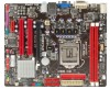
... / Mouse HDMI Port Back Panel I/O VGA Port DVI-D Port LAN Port USB Port Audio Jack Board Size 200(W) x 244 (L) mm OS Support Windows XP / Vista / 7 H55 HD SPEC x1 Connects to Power supply x1 Connects to Power supply x1 Connects to PS/2 Keyboard / Mouse x1 Connects to HDMI cable x1 Connect to... x1 Connect to DVI monitor x1 Connect to RJ-45 ethernet cable x4 Connect to USB devices x3 Provide Audio-In/Out and microphone connection Biostar reserves the right to add or remove support for any OS with or without notice 1.4 REAR PANEL CONNECTORS PS/2 Keyboard / Mouse LAN USBX2 HDMI DVI...
... / Mouse HDMI Port Back Panel I/O VGA Port DVI-D Port LAN Port USB Port Audio Jack Board Size 200(W) x 244 (L) mm OS Support Windows XP / Vista / 7 H55 HD SPEC x1 Connects to Power supply x1 Connects to Power supply x1 Connects to PS/2 Keyboard / Mouse x1 Connects to HDMI cable x1 Connect to... x1 Connect to DVI monitor x1 Connect to RJ-45 ethernet cable x4 Connect to USB devices x3 Provide Audio-In/Out and microphone connection Biostar reserves the right to add or remove support for any OS with or without notice 1.4 REAR PANEL CONNECTORS PS/2 Keyboard / Mouse LAN USBX2 HDMI DVI...

Setup Manual
Page 7
H55 HD CHAPTER 2: HARDWARE INSTALLATION 2.1 INSTALLING CENTRAL PROCESSING UNIT (CPU) Special Notice: Remove Pin Cap before installation, and make good preservation for future use. When the CPU is removed, cover the Pin Cap on the empty socket to ensure pin legs won't be damaged. Step 2: Remove the Pin Cap. 5 Step 1: Pull the socket locking lever out from the socket and then raise the lever up.
H55 HD CHAPTER 2: HARDWARE INSTALLATION 2.1 INSTALLING CENTRAL PROCESSING UNIT (CPU) Special Notice: Remove Pin Cap before installation, and make good preservation for future use. When the CPU is removed, cover the Pin Cap on the empty socket to ensure pin legs won't be damaged. Step 2: Remove the Pin Cap. 5 Step 1: Pull the socket locking lever out from the socket and then raise the lever up.

Setup Manual
Page 9
... 3 FAN RPM rate sense 4 Smart Fan Control SYS_FAN1: System Fan Header Pin Assignment 1 Ground 2 +12V 3 FAN RPM rate sense 3 1 Note: CPU_FAN1 supports 4-pin head connector; H55 HD 2.2 FAN HEADERS These fan headers support cooling-fans built in the computer.
... 3 FAN RPM rate sense 4 Smart Fan Control SYS_FAN1: System Fan Header Pin Assignment 1 Ground 2 +12V 3 FAN RPM rate sense 3 1 Note: CPU_FAN1 supports 4-pin head connector; H55 HD 2.2 FAN HEADERS These fan headers support cooling-fans built in the computer.

Setup Manual
Page 11
B. X, not installed.) The DRAM bus width of the same density in pairs, shown in the table. Dual Channel Status DDR3_A1 DDR3_B1 Disabled O X Disabled X O Enabled O O (O means memory installed; C. Memory Capacity DIMM Socket Location DDR3_A1 DDR3_B1 DDR3 Module 512MB/1GB/2GB/4GB 512MB/1GB/2GB/4GB H55 HD Total Memory Size Max is 8GB. Dual Channel Memory Installation Please refer to the following requirements to activate Dual Channel function: Install memory module of the memory module must be the same(x8 or x16) 9
B. X, not installed.) The DRAM bus width of the same density in pairs, shown in the table. Dual Channel Status DDR3_A1 DDR3_B1 Disabled O X Disabled X O Enabled O O (O means memory installed; C. Memory Capacity DIMM Socket Location DDR3_A1 DDR3_B1 DDR3 Module 512MB/1GB/2GB/4GB 512MB/1GB/2GB/4GB H55 HD Total Memory Size Max is 8GB. Dual Channel Memory Installation Please refer to the following requirements to activate Dual Channel function: Install memory module of the memory module must be the same(x8 or x16) 9

Setup Manual
Page 13
... 7 Ground 8 PW_OK 9 Standby Voltage+5V 10 +12V 11 +12V 12 +3.3V ATXPWR2: ATX Power Source Connector Connecting this connector provides +12V to CPU power circuit. H55 HD ATXPWR1: ATX Power Source Connector This connector is for 24-pin power connector on the system, please make sure that both ATXPWR1 and ATXPWR2 connectors...
... 7 Ground 8 PW_OK 9 Standby Voltage+5V 10 +12V 11 +12V 12 +3.3V ATXPWR2: ATX Power Source Connector Connecting this connector provides +12V to CPU power circuit. H55 HD ATXPWR1: ATX Power Source Connector This connector is for 24-pin power connector on the system, please make sure that both ATXPWR1 and ATXPWR2 connectors...

Setup Manual
Page 15
H55 HD CHAPTER 3: HEADERS & JUMPERS SETUP 3.1 HOW TO SETUP JUMPERS The illustration shows how to connect the PC case's front panel switch functions. It allows user to ...
H55 HD CHAPTER 3: HEADERS & JUMPERS SETUP 3.1 HOW TO SETUP JUMPERS The illustration shows how to connect the PC case's front panel switch functions. It allows user to ...

Setup Manual
Page 17
This header allows only HD audio front panel connector, not AC'97. 2 10 1 9 Pin Assignment 1 Mic Left in 2 Ground 3 Mic Right in 4 GPIO 5 Right line in 6 Jack Sense 7 Front Sense 8 Key 9 Left line in 10 Jack Sense JSPDIFOUT1: Digital Audio-out Connector This connector allows user to connect the front audio output cable with the PC front panel. Pin Assignment 1 +5V 2 SPDIF_OUT 3 Ground 1 3 15 H55 HD F_AUDIO1: Front Panel Audio Header This header allows user to connect the PCI bracket SPDIF output header.
This header allows only HD audio front panel connector, not AC'97. 2 10 1 9 Pin Assignment 1 Mic Left in 2 Ground 3 Mic Right in 4 GPIO 5 Right line in 6 Jack Sense 7 Front Sense 8 Key 9 Left line in 10 Jack Sense JSPDIFOUT1: Digital Audio-out Connector This connector allows user to connect the front audio output cable with the PC front panel. Pin Assignment 1 +5V 2 SPDIF_OUT 3 Ground 1 3 15 H55 HD F_AUDIO1: Front Panel Audio Header This header allows user to connect the PCI bracket SPDIF output header.

Setup Manual
Page 19
... damaging the motherboard. 3 1 Pin 1-2 Close: Normal Operation (Default). 3 1 3 1 Pin 2-3 Close: Clear CMOS data. ※ Clear CMOS Procedures: 1. Please carefully follow the procedures to "Pin 1-2 close ". 3. H55 HD JCMOS1: Clear CMOS Header Placing the jumper on the AC. 6. Wait for infrared remote control and communication. 26 15 Pin Assignment 1 IrDA serial input 2 Ground...
... damaging the motherboard. 3 1 Pin 1-2 Close: Normal Operation (Default). 3 1 3 1 Pin 2-3 Close: Clear CMOS data. ※ Clear CMOS Procedures: 1. Please carefully follow the procedures to "Pin 1-2 close ". 3. H55 HD JCMOS1: Clear CMOS Header Placing the jumper on the AC. 6. Wait for infrared remote control and communication. 26 15 Pin Assignment 1 IrDA serial input 2 Ground...

Setup Manual
Page 21
... the i nformation which is a convenient utility that you must provide. The drivers installation program would be able to contact with our Tech-Support system. 4.2 SOFTWARE H55 HD Installing Software 1.
... the i nformation which is a convenient utility that you must provide. The drivers installation program would be able to contact with our Tech-Support system. 4.2 SOFTWARE H55 HD Installing Software 1.

Setup Manual
Page 23
Choose the position to update your motherboard BIOS under Windows system. H55 HD BIOS Update BIOS Update is a convenient utility which allows you to save file and enter file name. (We recommend that the file name should be English/number and no longer than 7 characters.) Then click Save. 21 AWARD BIOS Show current BIOS information AMI BIOS Clear CMOS function (Only for AWARD BIOS) Save current BIOS to a .bin file Update BIOS with a BIOS file Once click on this button, the saving dialog will show.
Choose the position to update your motherboard BIOS under Windows system. H55 HD BIOS Update BIOS Update is a convenient utility which allows you to save file and enter file name. (We recommend that the file name should be English/number and no longer than 7 characters.) Then click Save. 21 AWARD BIOS Show current BIOS information AMI BIOS Clear CMOS function (Only for AWARD BIOS) Save current BIOS to a .bin file Update BIOS with a BIOS file Once click on this button, the saving dialog will show.

Setup Manual
Page 25
... the system may not power on again. Wait for seconds, that means the CPU protection function has been activated. When the CPU is rotated normally. 3. H55 HD 4.3 EXTRA INFORMATION CPU Overheated If the system shutdown automatically after power on system for seconds. 3.
... the system may not power on again. Wait for seconds, that means the CPU protection function has been activated. When the CPU is rotated normally. 3. H55 HD 4.3 EXTRA INFORMATION CPU Overheated If the system shutdown automatically after power on system for seconds. 3.

Setup Manual
Page 27
... integrated part of the system board, the board may be faulty. 25 If the video adapter is an add-in card. 4.4 AMI BIOS BEEP CODE H55 HD Boot Block Beep Codes Number of Beeps Description 1 No media present. (Insert diskette in floppy drive A:) 2 "AMIBOOT.ROM" file not found in root directory of...
... integrated part of the system board, the board may be faulty. 25 If the video adapter is an add-in card. 4.4 AMI BIOS BEEP CODE H55 HD Boot Block Beep Codes Number of Beeps Description 1 No media present. (Insert diskette in floppy drive A:) 2 "AMIBOOT.ROM" file not found in root directory of...

Setup Manual
Page 29
H55 HD This page is intentionally left blank. 27
H55 HD This page is intentionally left blank. 27
