Bios Setup
Page 30
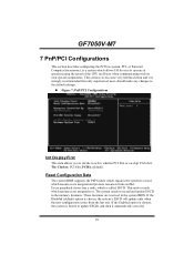
...PCIEx (default). These locations are assigned and protects resources from the last one. This section covers some very technical items and it . GF7050V-M7 7 PnP/PCI Configurations This section describes configuring the PCI bus system. The system needs to record and update ESCD to active whether ... system to operate at speeds nearing the speed of the CPU itself uses when communicating with its own special components. Reset Configuration Data The system BIOS supports the PnP feature which is chosen, the system's ESCD will update only when the new configuration varies from conflict...
...PCIEx (default). These locations are assigned and protects resources from the last one. This section covers some very technical items and it . GF7050V-M7 7 PnP/PCI Configurations This section describes configuring the PCI bus system. The system needs to record and update ESCD to active whether ... system to operate at speeds nearing the speed of the CPU itself uses when communicating with its own special components. Reset Configuration Data The system BIOS supports the PnP feature which is chosen, the system's ESCD will update only when the new configuration varies from conflict...

Setup Manual
Page 18
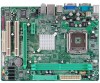
Set the jumper to "Pin 1-2 close ". 3. Set the jumper to "Pin 2-3 close ". 5. Power on pin2-3, it allows user to restore the BIOS saf e setting and the CMOS data, please carefully f ollow the procedures to avoid damaging the motherboard. 13 Pin 1-2 Close: Normal Operation (Default). 13 13 Pin 2-3 ... 1 Left Channel Input 2 Ground 3 Ground 4 Right Channel Input JCMO S1: Cle ar CMOS Heade r By placing the jumper on the AC. 6. Remov e AC power line. 2. Reset your desired password or clear the CMOS data. 16
Set the jumper to "Pin 1-2 close ". 3. Set the jumper to "Pin 2-3 close ". 5. Power on pin2-3, it allows user to restore the BIOS saf e setting and the CMOS data, please carefully f ollow the procedures to avoid damaging the motherboard. 13 Pin 1-2 Close: Normal Operation (Default). 13 13 Pin 2-3 ... 1 Left Channel Input 2 Ground 3 Ground 4 Right Channel Input JCMO S1: Cle ar CMOS Heade r By placing the jumper on the AC. 6. Remov e AC power line. 2. Reset your desired password or clear the CMOS data. 16
