Bios Setup
Page 2
... manual will to CMOS RAM. EPA Green PC Support This PHOENIX-AWARD BIOS supports Version 1.03 of the EPA Green PC spec ification. Power to the hard disk drives and video monitors can do without accessing programs from a disk. Some additional features, such as keyboard, mouse, serial ports and disk drives. GF7050V-M7... BIOS Setup Introduction The purpose of this manual is turned off.
... manual will to CMOS RAM. EPA Green PC Support This PHOENIX-AWARD BIOS supports Version 1.03 of the EPA Green PC spec ification. Power to the hard disk drives and video monitors can do without accessing programs from a disk. Some additional features, such as keyboard, mouse, serial ports and disk drives. GF7050V-M7... BIOS Setup Introduction The purpose of this manual is turned off.
Bios Setup
Page 4
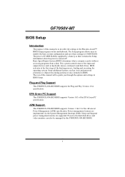
... will appear on board may be slightly different from several setup functions. GF7050V-M7 1 Main Menu Once you to accept and enter the sub-menu. !! WARNING !! The BIOS information described in this manual. „ Figure 1: Main Menu Standard CMOS Features This submenu contains ...industry standard configurable options. 3 Use the arrow keys to select among the items and press to select from this manual (Figure 1, 2, 3, 4, 5, 6, 7, 8, 9) ...
... will appear on board may be slightly different from several setup functions. GF7050V-M7 1 Main Menu Once you to accept and enter the sub-menu. !! WARNING !! The BIOS information described in this manual. „ Figure 1: Main Menu Standard CMOS Features This submenu contains ...industry standard configurable options. 3 Use the arrow keys to select among the items and press to select from this manual (Figure 1, 2, 3, 4, 5, 6, 7, 8, 9) ...
Bios Setup
Page 31
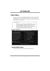
... to configure the system interrupts. By Choosing "Manual", the user will allow you to assign IRQ & DMA for ISA PnP add-on cards. When you press the "Press Enter" tag, you to the PCI Bus or provides for add-on cards and peripherals. GF7050V-M7 "Disabled" mode. IRQ-5 assigned to PCI ...Device IRQ-7 assigned to PCI Device IRQ-9 assigned to PCI Device IRQ-10 assigned to PCI Device IRQ-11 assigned to PCI Device IRQ-14 assigned to PCI Device IRQ-15 assigned to " Manual". The above settings will ...
... to configure the system interrupts. By Choosing "Manual", the user will allow you to assign IRQ & DMA for ISA PnP add-on cards. When you press the "Press Enter" tag, you to the PCI Bus or provides for add-on cards and peripherals. GF7050V-M7 "Disabled" mode. IRQ-5 assigned to PCI ...Device IRQ-7 assigned to PCI Device IRQ-9 assigned to PCI Device IRQ-10 assigned to PCI Device IRQ-11 assigned to PCI Device IRQ-14 assigned to PCI Device IRQ-15 assigned to " Manual". The above settings will ...

Bios Setup
Page 37
The Choices: Optimal (default), Expert tCL (CAS Latency) The Choices: Auto (default), 3 CLK ~ 6 CLK. tRP The Choices: Auto (default), 3 CLK ~ 6 CLK. tRCD The Choices: Auto (default), 3 CLK ~ 6 CLK. tRAS The Choices: Auto (default), 5 CLK ~ 18 CLK. GF7050V-M7 Memory Timing Setting Memory Timing Setting This item allows you to choose to manually or automatically regulate the DDR T imin g. Command Per Clock (CMD) The Choices: Auto (default), 1T, 2T. 36
The Choices: Optimal (default), Expert tCL (CAS Latency) The Choices: Auto (default), 3 CLK ~ 6 CLK. tRP The Choices: Auto (default), 3 CLK ~ 6 CLK. tRCD The Choices: Auto (default), 3 CLK ~ 6 CLK. tRAS The Choices: Auto (default), 5 CLK ~ 18 CLK. GF7050V-M7 Memory Timing Setting Memory Timing Setting This item allows you to choose to manually or automatically regulate the DDR T imin g. Command Per Clock (CMD) The Choices: Auto (default), 1T, 2T. 36
Setup Manual
Page 1
... his equipment generates , uses , and c an radiate radio frequency energy and, if not ins talled and used in a particular ins tallation. GF7050V-M7 Setup Manual FCC Information and Copyright This equipment has been tes ted and found in this publication and to make c hanges to provide reasonable protec tion against...no guarantee that interference will not be c hanged without notice and we will not occur in accordance with respec t to revise this user's manual. D uplication of this publication, in part or in whole, is subject to be res ponsible for any mis takes found to comply ...
... his equipment generates , uses , and c an radiate radio frequency energy and, if not ins talled and used in a particular ins tallation. GF7050V-M7 Setup Manual FCC Information and Copyright This equipment has been tes ted and found in this publication and to make c hanges to provide reasonable protec tion against...no guarantee that interference will not be c hanged without notice and we will not occur in accordance with respec t to revise this user's manual. D uplication of this publication, in part or in whole, is subject to be res ponsible for any mis takes found to comply ...
Setup Manual
Page 3
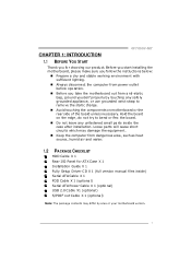
...; Keep the compute r from dange rous a rea, such as hea t source , humid air and wate r. 1.2 PACKAGE CHECKLIST HDD Cable X 1 Rear I/O Panel for choosing our product. GF7050V-M7 CHAPTER 1: INTRODUCTION 1.1 BEFORE YOU START Thank you take the mothe rboard out from anti-static bag, ground yourse lf prope rly by area or your... ct the compute r from powe r outle t be fore ope ration. „ Before you for ATX Case X 1 Installation Guide X 1 Fully Se tup Drive r C D X 1 (full ve rsion manual files inside the case afte r installation.
...; Keep the compute r from dange rous a rea, such as hea t source , humid air and wate r. 1.2 PACKAGE CHECKLIST HDD Cable X 1 Rear I/O Panel for choosing our product. GF7050V-M7 CHAPTER 1: INTRODUCTION 1.1 BEFORE YOU START Thank you take the mothe rboard out from anti-static bag, ground yourse lf prope rly by area or your... ct the compute r from powe r outle t be fore ope ration. „ Before you for ATX Case X 1 Installation Guide X 1 Fully Se tup Drive r C D X 1 (full ve rsion manual files inside the case afte r installation.
Setup Manual
Page 4
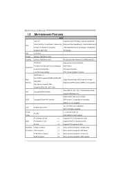
SATA Version 2.0specificationcompliant. Motherboard Manual 1.3 MOT HERBOARD FEAT URES SPEC CPU FSB LGA 775 Supports Hyper-Threading / Execute Disable Bit / Intel Core2Duo / Core2Quad / Celeron 4xx / Enhanced Intel SpeedStep® / Intel ...
SATA Version 2.0specificationcompliant. Motherboard Manual 1.3 MOT HERBOARD FEAT URES SPEC CPU FSB LGA 775 Supports Hyper-Threading / Execute Disable Bit / Intel Core2Duo / Core2Quad / Celeron 4xx / Enhanced Intel SpeedStep® / Intel ...
Setup Manual
Page 6
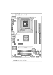
Motherboard Manual 1.5 MOT HERBOARD LAYOUT COMJC1OM1 JKB MS1 JKB_PWR1 JATXPWR3 LGA775 CPU1 JCFAN1 JATXPWR2 JV GA1 DIMMA1 DIMMA2 IDE1 JUSB1 JUSBLAN1 JUSB_PWR1 JAUDIO1 LAN JCDIN1 GeForce 7050/ nForce 610i PEX1_1 BIOS Super I/O PEX16_1 Co d ec PCI1 JSPDIF_OUT1 PCI2 JPRNT1 FDD1 SATA1 SATA2 SATA3 SATA4 BAT1 JCMOS1 JUSB_PWR2 JUSB2 JUSB3 JPANEL1 JSFAN1 JAUDIOF1 Not e: ■ repre sents the 1st pin. 4
Motherboard Manual 1.5 MOT HERBOARD LAYOUT COMJC1OM1 JKB MS1 JKB_PWR1 JATXPWR3 LGA775 CPU1 JCFAN1 JATXPWR2 JV GA1 DIMMA1 DIMMA2 IDE1 JUSB1 JUSBLAN1 JUSB_PWR1 JAUDIO1 LAN JCDIN1 GeForce 7050/ nForce 610i PEX1_1 BIOS Super I/O PEX16_1 Co d ec PCI1 JSPDIF_OUT1 PCI2 JPRNT1 FDD1 SATA1 SATA2 SATA3 SATA4 BAT1 JCMOS1 JUSB_PWR2 JUSB2 JUSB3 JPANEL1 JSFAN1 JAUDIOF1 Not e: ■ repre sents the 1st pin. 4

Setup Manual
Page 8
Motherboard Manual Step 2: Look for the triangular cut edge on socket, and the golden dot on the retention frame. Step 4: Put the CPU Fan and heatsink assembly on the CPU and buckle it on CPU should point forwards this triangular cut edge. This completes the installation. 6 Step 2-1: Step 2-2: Step 3: Hold the CPU down firmly, and then lower the lever to locked position to complete the installation. Connect the CPU FAN power cable into the JCFAN1. The CPU will fit only in the correct orientation.
Motherboard Manual Step 2: Look for the triangular cut edge on socket, and the golden dot on the retention frame. Step 4: Put the CPU Fan and heatsink assembly on the CPU and buckle it on CPU should point forwards this triangular cut edge. This completes the installation. 6 Step 2-1: Step 2-2: Step 3: Hold the CPU down firmly, and then lower the lever to locked position to complete the installation. Connect the CPU FAN power cable into the JCFAN1. The CPU will fit only in the correct orientation.

Setup Manual
Page 10
Memory Modules 1. D IMMA1 D IMMA2 Motherboard Manual 2.3 INST ALLING SYST EM MEMORY A. Align a DIMM on the slot such that the notch on the DIMM matches the break on the Slot. 8 Unlock a DIMM slot by pressing the retaining clips outward.
Memory Modules 1. D IMMA1 D IMMA2 Motherboard Manual 2.3 INST ALLING SYST EM MEMORY A. Align a DIMM on the slot such that the notch on the DIMM matches the break on the Slot. 8 Unlock a DIMM slot by pressing the retaining clips outward.

Setup Manual
Page 12
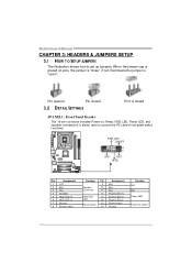
Motherboard Manual 2.4 CONNECT ORS AND SLOT S FDD1: Floppy Disk Conne ctor The motherboard prov ides a standard floppy disk connector that prov ides PIO Mode 0~4, Bus Master, and Ultra DMA 33/66/100/133 f unctionality. The IDE connector can connect a master and a slave drive, so y ou can connect up to two hard disk driv es. 40 39 2 1 10 This connector supports the prov ided f loppy drive ribbon cables. 2 34 1 33 IDE1: Hard Disk Conne ctor The motherboard has a 32-bit Enhanced PCI IDE Controller that supports 360K, 720K, 1.2M, 1.44M and 2.88M floppy disk ty pes.
Motherboard Manual 2.4 CONNECT ORS AND SLOT S FDD1: Floppy Disk Conne ctor The motherboard prov ides a standard floppy disk connector that prov ides PIO Mode 0~4, Bus Master, and Ultra DMA 33/66/100/133 f unctionality. The IDE connector can connect a master and a slave drive, so y ou can connect up to two hard disk driv es. 40 39 2 1 10 This connector supports the prov ided f loppy drive ribbon cables. 2 34 1 33 IDE1: Hard Disk Conne ctor The motherboard has a 32-bit Enhanced PCI IDE Controller that supports 360K, 720K, 1.2M, 1.44M and 2.88M floppy disk ty pes.
Setup Manual
Page 14
... AIL SETT INGS Pin1-2 closed JPANEL1: Front Panel Heade r This 16-pin connector includes Power-on, Reset, HDD LED, Power LED, and speaker connections. Motherboard Manual CHAPTER 3: HEADERS & JUMPERS SETUP 3.1 HOW T O SET UP JUMPERS The illustration shows how to connect the PC case's f ront panel switch f unctions.
... AIL SETT INGS Pin1-2 closed JPANEL1: Front Panel Heade r This 16-pin connector includes Power-on, Reset, HDD LED, Power LED, and speaker connections. Motherboard Manual CHAPTER 3: HEADERS & JUMPERS SETUP 3.1 HOW T O SET UP JUMPERS The illustration shows how to connect the PC case's f ront panel switch f unctions.

Setup Manual
Page 16
..., and also can be connected with transfer rate of 3Gb/s. SATA1 SATA 2 SATA3 S ATA4 1 4 7 Pin Assignment 1 Ground 2 TX+ 3 TX4 Ground 5 RX6 RX+ 7 Ground 14 Motherboard Manual JUSB2/JUSB3: Heade rs for USB 2.0 Ports at Front Panel This motherboard prov ides 2 USB 2.0 headers, which allows user to SATA Controller with 4 channels SATA...
..., and also can be connected with transfer rate of 3Gb/s. SATA1 SATA 2 SATA3 S ATA4 1 4 7 Pin Assignment 1 Ground 2 TX+ 3 TX4 Ground 5 RX6 RX+ 7 Ground 14 Motherboard Manual JUSB2/JUSB3: Heade rs for USB 2.0 Ports at Front Panel This motherboard prov ides 2 USB 2.0 headers, which allows user to SATA Controller with 4 channels SATA...

Setup Manual
Page 18
...; Clear CMOS Proce dures: 1. Reset your desired password or clear the CMOS data. 16 Set the jumper to "Pin 2-3 close ". 5. Remov e AC power line. 2. Motherboard Manual JCDIN1: CD-RO M Audio-in Connector This connector allows user to connect the audio source f rom the variaty dev ices, like CD-ROM, DVD-ROM...
...; Clear CMOS Proce dures: 1. Reset your desired password or clear the CMOS data. 16 Set the jumper to "Pin 2-3 close ". 5. Remov e AC power line. 2. Motherboard Manual JCDIN1: CD-RO M Audio-in Connector This connector allows user to connect the audio source f rom the variaty dev ices, like CD-ROM, DVD-ROM...

Setup Manual
Page 20
Pin Assignment 1 -Strobe 2 -ALF 3 Data 0 4 -Error 5 Data 1 6 -Init 7 Data 2 8 -Scltin 9 Data 3 10 Ground 11 Data 4 12 Ground 13 Data 5 2 1 25 Pin Assignment 14 Ground 15 Data 6 16 Ground 17 Data 7 18 Ground 19 -ACK 20 Ground 21 Busy 22 Ground 23 PE 24 Ground 25 SCLT 26 Key 18 Motherboard Manual JPRNT1: Printe r Port Connector This header allows you to connector printer on the PC.
Pin Assignment 1 -Strobe 2 -ALF 3 Data 0 4 -Error 5 Data 1 6 -Init 7 Data 2 8 -Scltin 9 Data 3 10 Ground 11 Data 4 12 Ground 13 Data 5 2 1 25 Pin Assignment 14 Ground 15 Data 6 16 Ground 17 Data 7 18 Ground 19 -ACK 20 Ground 21 Busy 22 Ground 23 PE 24 Ground 25 SCLT 26 Key 18 Motherboard Manual JPRNT1: Printe r Port Connector This header allows you to connector printer on the PC.

Setup Manual
Page 22
... 1: Every read and write is ideal f or small databases or any other application that eliminates tedious manual backups to the other drive. Drawbacks: Requires 2 driv es for the storage space of automatic backup that requires f ault tolerance and minimal capacity. ...
... 1: Every read and write is ideal f or small databases or any other application that eliminates tedious manual backups to the other drive. Drawbacks: Requires 2 driv es for the storage space of automatic backup that requires f ault tolerance and minimal capacity. ...

Setup Manual
Page 24
...setup guide will see the following window after you ins ert the Driver CD, please use file brows er to open the manual file. C. You will list the software available for your motherboard and operating system. Note: You will auto detect your motherboard and operating... SETUP.EXE under your optical drive. Click on each software title to browse for better system performance. Click on the Manual icon to launch the installation program. Motherboard Manual CHAPTER 5: USEFUL HELP 5.1 DRIVER INST ALLAT ION NOT E After you installed your operating system, please insert the Fully...
...setup guide will see the following window after you ins ert the Driver CD, please use file brows er to open the manual file. C. You will list the software available for your motherboard and operating system. Note: You will auto detect your motherboard and operating... SETUP.EXE under your optical drive. Click on each software title to browse for better system performance. Click on the Manual icon to launch the installation program. Motherboard Manual CHAPTER 5: USEFUL HELP 5.1 DRIVER INST ALLAT ION NOT E After you installed your operating system, please insert the Fully...

Setup Manual
Page 26
Motherboard Manual 5.4 TROUBLESHOOT ING Probable Solution 1. Using even pressure on both ends are lit, and hard driv e is spinning. driv e, can be booted f rom optical driv e. 2. Backing ...
Motherboard Manual 5.4 TROUBLESHOOT ING Probable Solution 1. Using even pressure on both ends are lit, and hard driv e is spinning. driv e, can be booted f rom optical driv e. 2. Backing ...

