
Setup Manual
Page 2
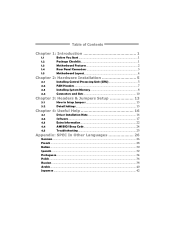
Table of Contents Chapter 1: Introduction 1 1.1 Before You Start 1 1.2 Package Checklist 1 1.3 Motherboard Features 2 1.4 Rear Panel Connectors 3 1.5 Motherboard Layout 4 Chapter 2: Hardware Installation 5 2.1 Installing Central Processing Unit (CPU 5 2.2 FAN Headers 7 2.3 Installing System Memory 8 2.4 Connectors and Slots 10 Chapter 3: Headers & Jumpers Setup 13 3.1 How to ...
Table of Contents Chapter 1: Introduction 1 1.1 Before You Start 1 1.2 Package Checklist 1 1.3 Motherboard Features 2 1.4 Rear Panel Connectors 3 1.5 Motherboard Layout 4 Chapter 2: Hardware Installation 5 2.1 Installing Central Processing Unit (CPU 5 2.2 FAN Headers 7 2.3 Installing System Memory 8 2.4 Connectors and Slots 10 Chapter 3: Headers & Jumpers Setup 13 3.1 How to ...
Setup Manual
Page 3
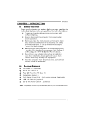
CHAPTER 1: INTRODUCTION G41D3C 1.1 BEFORE YOU START Thank you take the motherboard out from dangerous area, such as heat source, humid air and water. 1.2 PACKAGE CHECKLIST IDE Cable X 1 (optional) Serial ATA Cable X 2 Rear I/O Panel for choosing our... grounded appliance, or use grounded wrist strap to remove the static charge. „ Avoid touching the components on motherboard or the rear side of the board unless necessary. Before you start installing the motherboard, please make sure you follow the instructions below: „ Prepare a dry and stable working environment with sufficient ...
CHAPTER 1: INTRODUCTION G41D3C 1.1 BEFORE YOU START Thank you take the motherboard out from dangerous area, such as heat source, humid air and water. 1.2 PACKAGE CHECKLIST IDE Cable X 1 (optional) Serial ATA Cable X 2 Rear I/O Panel for choosing our... grounded appliance, or use grounded wrist strap to remove the static charge. „ Avoid touching the components on motherboard or the rear side of the board unless necessary. Before you start installing the motherboard, please make sure you follow the instructions below: „ Prepare a dry and stable working environment with sufficient ...
Setup Manual
Page 4
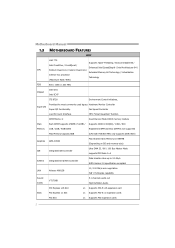
... Slot x1 Supports PCI-E x16 expansion card Slots PCI Express x1 Slot x1 Supports PCI-E x1 expansion cards PCI Slot x1 Supports PCI expansion cards 2 Motherboard Manual 1.3 MOTHERBOARD FEATURES SPEC LGA 775 Supports Hyper-Threading / Execute Disable Bit / Intel Core2Duo / Core2Quad / Enhanced Intel SpeedStep® / Intel Architecture-64 / CPU Pentium Dual-Core...
... Slot x1 Supports PCI-E x16 expansion card Slots PCI Express x1 Slot x1 Supports PCI-E x1 expansion cards PCI Slot x1 Supports PCI expansion cards 2 Motherboard Manual 1.3 MOTHERBOARD FEATURES SPEC LGA 775 Supports Hyper-Threading / Execute Disable Bit / Intel Core2Duo / Core2Quad / Enhanced Intel SpeedStep® / Intel Architecture-64 / CPU Pentium Dual-Core...
Setup Manual
Page 6
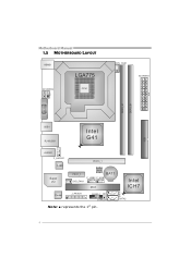
Motherboard Manual 1.5 MOTHERBOARD LAYOUT KBMS1 LGA775 ATX PW R2 CPU1 CPU _FA N1 ATX PW R1 D DR3_A 1 D DR3_B 1 VG A1 ID E1 USB1 RJ 45U SB 1 Intel G41 AU DIO1 F _AU DI O1 LAN Super I/O PEX16_1 PEX1_1 SYS_FAN1 BIOS BAT1 F_USB2 F_USB1 PCI1 Intel ICH7 SATA1 Codec J_PR INT 1 PAN EL1 JC MOS1 SATA2 Note: ■ represents the 1st pin. 4
Motherboard Manual 1.5 MOTHERBOARD LAYOUT KBMS1 LGA775 ATX PW R2 CPU1 CPU _FA N1 ATX PW R1 D DR3_A 1 D DR3_B 1 VG A1 ID E1 USB1 RJ 45U SB 1 Intel G41 AU DIO1 F _AU DI O1 LAN Super I/O PEX16_1 PEX1_1 SYS_FAN1 BIOS BAT1 F_USB2 F_USB1 PCI1 Intel ICH7 SATA1 Codec J_PR INT 1 PAN EL1 JC MOS1 SATA2 Note: ■ represents the 1st pin. 4
Setup Manual
Page 8
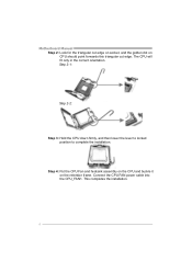
Connect the CPU FAN power cable into the CPU_FAN1. Step 2-1: Step 2-2: Step 3: Hold the CPU down firmly, and then lower the lever to locked position to complete the installation. This completes the installation. 6 Motherboard Manual Step 2: Look for the triangular cut edge. Step 4: Put the CPU Fan and heatsink assembly on the CPU and buckle it on CPU should point forwards this triangular cut edge on socket, and the golden dot on the retention frame. The CPU will fit only in the correct orientation.
Connect the CPU FAN power cable into the CPU_FAN1. Step 2-1: Step 2-2: Step 3: Hold the CPU down firmly, and then lower the lever to locked position to complete the installation. This completes the installation. 6 Motherboard Manual Step 2: Look for the triangular cut edge. Step 4: Put the CPU Fan and heatsink assembly on the CPU and buckle it on CPU should point forwards this triangular cut edge on socket, and the golden dot on the retention frame. The CPU will fit only in the correct orientation.
Setup Manual
Page 10
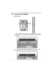
D DR 3 _A1 D DR 3 _B1 Motherboard Manual 2.3 INSTALLING SYSTEM MEMORY A. Unlock a DIMM slot by pressing the retaining clips outward. Insert the DIMM vertically and firmly into the slot until the retaining chip snap back in place and the DIMM is properly seated. 8 DDR3 module 1. Align a DIMM on the slot so that the notch on the DIMM matches the break on the Slot. 2.
D DR 3 _A1 D DR 3 _B1 Motherboard Manual 2.3 INSTALLING SYSTEM MEMORY A. Unlock a DIMM slot by pressing the retaining clips outward. Insert the DIMM vertically and firmly into the slot until the retaining chip snap back in place and the DIMM is properly seated. 8 DDR3 module 1. Align a DIMM on the slot so that the notch on the DIMM matches the break on the Slot. 2.
Setup Manual
Page 12
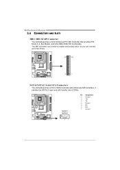
The IDE connector can connect a master and a slave drive, so you can connect up to two drives. 40 39 2 1 SATA1/SATA2: Serial ATA Connectors The motherboard has a PCI to SATA Controller with 2channels SATA interface, it satisfies the SATA 2.0 spec and with transfer rate of 3Gb/s. SATA 1 SATA 2 Pin Assignment 1 Ground 2 TX+ 3 TX4 Ground 5 RX6 RX+ 7 Ground 14 7 10 Motherboard Manual 2.4 CONNECTORS AND SLOTS IDE1: IDE/ATAPI Connector The motherboard has a 32-bit Enhanced PCI IDE Controller that provides PIO Mode 0~4, Bus Master, and Ultra DMA 33/66/100 functionality.
The IDE connector can connect a master and a slave drive, so you can connect up to two drives. 40 39 2 1 SATA1/SATA2: Serial ATA Connectors The motherboard has a PCI to SATA Controller with 2channels SATA interface, it satisfies the SATA 2.0 spec and with transfer rate of 3Gb/s. SATA 1 SATA 2 Pin Assignment 1 Ground 2 TX+ 3 TX4 Ground 5 RX6 RX+ 7 Ground 14 7 10 Motherboard Manual 2.4 CONNECTORS AND SLOTS IDE1: IDE/ATAPI Connector The motherboard has a 32-bit Enhanced PCI IDE Controller that provides PIO Mode 0~4, Bus Master, and Ultra DMA 33/66/100 functionality.
Setup Manual
Page 14
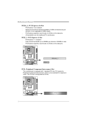
... the traditional PCI architecture. PCI1 12 Data transfer bandwidth up to 250MB/s per direction, for expansion cards. PEX16_1 PEX1_1 PCI1: Peripheral Component Interconnect Slot This motherboard is designated as 32 bits. PCI stands for Peripheral Component Interconnect, and it is a bus standard for an aggregate of 2.5Gb/s on the data pins...
... the traditional PCI architecture. PCI1 12 Data transfer bandwidth up to 250MB/s per direction, for expansion cards. PEX16_1 PEX1_1 PCI1: Peripheral Component Interconnect Slot This motherboard is designated as 32 bits. PCI stands for Peripheral Component Interconnect, and it is a bus standard for an aggregate of 2.5Gb/s on the data pins...
Setup Manual
Page 16
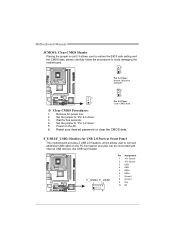
...panel, and also can be connected with internal USB devices, like USB card reader. F_USB1/F_USB2: Headers for five seconds. 4. Motherboard Manual JCMOS1: Clear CMOS Header Placing the jumper on pin2-3 allows user to restore the BIOS safe setting and the CMOS data... carefully follow the procedures to connect additional USB cable on the AC. 6. Wait for USB 2.0 Ports at Front Panel This motherboard provides 2 USB 2.0 headers, which allows user to avoid damaging the motherboard. 3 1 Pin 1-2 Close: Normal Operation (Default). 3 1 3 Pin 2-3 Close: 1 Clear CMOS data. ※ Clear CMOS...
...panel, and also can be connected with internal USB devices, like USB card reader. F_USB1/F_USB2: Headers for five seconds. 4. Motherboard Manual JCMOS1: Clear CMOS Header Placing the jumper on pin2-3 allows user to restore the BIOS safe setting and the CMOS data... carefully follow the procedures to connect additional USB cable on the AC. 6. Wait for USB 2.0 Ports at Front Panel This motherboard provides 2 USB 2.0 headers, which allows user to avoid damaging the motherboard. 3 1 Pin 1-2 Close: Normal Operation (Default). 3 1 3 Pin 2-3 Close: 1 Clear CMOS data. ※ Clear CMOS...
Setup Manual
Page 18
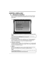
... optical drive. Note: If this window didn't show up after you insert the CD The setup guide will auto detect your motherboard and operating system. Software Installation To install the software, please click on each software title to browse for better system performance. ...Click on the Software icon. B. Note: You will list the software available for your motherboard and operating system. Driver Installation To install the driver, please click on the Manual icon to launch the installation program. C. Please ...
... optical drive. Note: If this window didn't show up after you insert the CD The setup guide will auto detect your motherboard and operating system. Software Installation To install the software, please click on each software title to browse for better system performance. ...Click on the Software icon. B. Note: You will list the software available for your motherboard and operating system. Driver Installation To install the driver, please click on the Manual icon to launch the installation program. C. Please ...
Setup Manual
Page 20
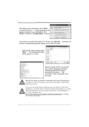
...third parties, so please feel free to provide your confirmation; We will see your default e-mail client application, you are not using eHot-Line service. Motherboard Manual After filling up this information to a .txt file, click "Save As..." Enter the file name and then click "Save". This information is also... concluded in the sent mail. Go to the following web http://www.biostar.com.tw/app/en-us/about/contact.php for your system information while using Outlook Express as your system information including...
...third parties, so please feel free to provide your confirmation; We will see your default e-mail client application, you are not using eHot-Line service. Motherboard Manual After filling up this information to a .txt file, click "Save As..." Enter the file name and then click "Save". This information is also... concluded in the sent mail. Go to the following web http://www.biostar.com.tw/app/en-us/about/contact.php for your system information while using Outlook Express as your system information including...
Setup Manual
Page 21
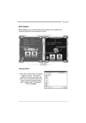
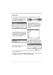
Choose the position to update your motherboard BIOS under Windows system. G41D3C BIOS Update BIOS Update is a convenient utility which allows you to save file and enter file name. (We recommend that the file name should be English/number and no longer than 7 characters.) Then click Save. 19 AWARD BIOS Show current BIOS information AMI BIOS Clear CMOS function (Only for AWARD BIOS) Online Update function (Only for AMI BIOS) Save current BIOS to a .bin file Update BIOS with a BIOS file Once click on this button, the saving dialog will show.
Choose the position to update your motherboard BIOS under Windows system. G41D3C BIOS Update BIOS Update is a convenient utility which allows you to save file and enter file name. (We recommend that the file name should be English/number and no longer than 7 characters.) Then click Save. 19 AWARD BIOS Show current BIOS information AMI BIOS Clear CMOS function (Only for AWARD BIOS) Online Update function (Only for AMI BIOS) Save current BIOS to a .bin file Update BIOS with a BIOS file Once click on this button, the saving dialog will show.
Setup Manual
Page 22
... to restart the system. In the BIOS setup, use the Load Optimized Defaults function and then Save and Exit Setup to the Backup BIOS procedure; Motherboard Manual Before doing this process may take minutes.
... to restart the system. In the BIOS setup, use the Load Optimized Defaults function and then Save and Exit Setup to the Backup BIOS procedure; Motherboard Manual Before doing this process may take minutes.
Setup Manual
Page 24
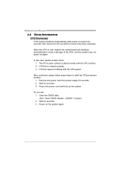
...on again. CPU fan is fulfilling with the CPU surface. 2. In this case, please double check: 1. The CPU cooler surface is over heated, the motherboard will shutdown automatically to relief the CPU protection function. 1. Plug in the power cord and boot up the system. Wait for seconds. 3. Wait for seconds... function has been activated. Power on the system again. 22 Or you can: 1. Clear the CMOS data. (See "Close CMOS Header: JCMOS1" section) 2. Motherboard Manual 4.3 EXTRA INFORMATION CPU Overheated If the system shutdown automatically after power on system for seconds. 2.
...on again. CPU fan is fulfilling with the CPU surface. 2. In this case, please double check: 1. The CPU cooler surface is over heated, the motherboard will shutdown automatically to relief the CPU protection function. 1. Plug in the power cord and boot up the system. Wait for seconds. 3. Wait for seconds... function has been activated. Power on the system again. 22 Or you can: 1. Clear the CMOS data. (See "Close CMOS Header: JCMOS1" section) 2. Motherboard Manual 4.3 EXTRA INFORMATION CPU Overheated If the system shutdown automatically after power on system for seconds. 2.
Setup Manual
Page 25
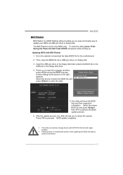
... that contains the BIOS file to enter the utility. 5. Select the proper BIOS file and press then to download the latest BIOS file for the motherboard. 2. Updating BIOS with FAT32/16 format and single partition. Go to the website to perform the BIOS update process. 6. Power on the right appears. BIOS.... 23 A select dialog as the picture on or reset the computer and then press during the Power-On Self Tests (POST) procedure while booting up. G41D3C BIO-Flasher BIO-Flasher is built in the BIOS chip. After the update process, the utility will ask you an easy and simple way to...
... that contains the BIOS file to enter the utility. 5. Select the proper BIOS file and press then to download the latest BIOS file for the motherboard. 2. Updating BIOS with FAT32/16 format and single partition. Go to the website to perform the BIOS update process. 6. Power on the right appears. BIOS.... 23 A select dialog as the picture on or reset the computer and then press during the Power-On Self Tests (POST) procedure while booting up. G41D3C BIO-Flasher BIO-Flasher is built in the BIOS chip. After the update process, the utility will ask you an easy and simple way to...
Setup Manual
Page 26
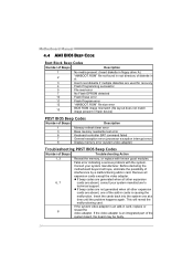
... reveal the malfunctioning card. If the system video adapter is an integrated part of the system board, the board may be faulty. 24 Motherboard Manual 4.4 AMI BIOS BEEP CODE Boot Block Beep Codes Number of Beeps Description 1 No media present. (Insert diskette in floppy drive A:)... causing the malfunction. Insert the cards back into the system one of interference by a malfunctioning add-in card. Before declaring the motherboard beyond all expansion cards except the video adapter. Consult your system manufacturer's technical support. z If beep codes are not generated when...
... reveal the malfunctioning card. If the system video adapter is an integrated part of the system board, the board may be faulty. 24 Motherboard Manual 4.4 AMI BIOS BEEP CODE Boot Block Beep Codes Number of Beeps Description 1 No media present. (Insert diskette in floppy drive A:)... causing the malfunction. Insert the cards back into the system one of interference by a malfunctioning add-in card. Before declaring the motherboard beyond all expansion cards except the video adapter. Consult your system manufacturer's technical support. z If beep codes are not generated when...
Bios Setup
Page 2
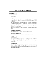
... protection or chipset fine-tuning options are supported. Sleep and Suspend power management modes are also included in the AMI BIOS Setup program on this motherboard. The power of CMOS RAM is supplied by a battery so that it retains the Setup information when the power is to guide you through the... to modify the basic system configuration and save these settings to the hard disk drives and video monitors can do without accessing programs from a disk. G41D3C BIOS Manual BIOS Setup Introduction The purpose of this manual is turned off.
... protection or chipset fine-tuning options are supported. Sleep and Suspend power management modes are also included in the AMI BIOS Setup program on this motherboard. The power of CMOS RAM is supplied by a battery so that it retains the Setup information when the power is to guide you through the... to modify the basic system configuration and save these settings to the hard disk drives and video monitors can do without accessing programs from a disk. G41D3C BIOS Manual BIOS Setup Introduction The purpose of this manual is turned off.
Bios Setup
Page 3
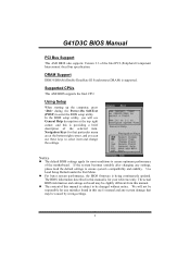
... utility, you can use these keys to be caused by wrong-settings. 2 z The content of the selected item. G41D3C BIOS Manual PCI Bus Support This AMI BIOS also supports Version 2.3 of the motherboard. DRAM Support DDR3 SDRAM (Double Data Rate III Synchronous DRAM) is being continuously updated. Use Load Setup Default under...
... utility, you can use these keys to be caused by wrong-settings. 2 z The content of the selected item. G41D3C BIOS Manual PCI Bus Support This AMI BIOS also supports Version 2.3 of the motherboard. DRAM Support DDR3 SDRAM (Double Data Rate III Synchronous DRAM) is being continuously updated. Use Load Setup Default under...
Bios Setup
Page 14
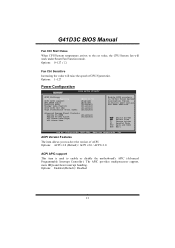
...will raise the speed of ACPI. Options: 0~127 (℃) Fan Ctrl Sensitive Increasing the value will work under Smart Fan Function mode. G41D3C BIOS Manual Fan Ctrl Start Value When CPU/System temperature arrives to select the version of CPU/System fan. Options: Enabled (Default) /...# [Disabled] Resume On RTC Alarm [Disabled] RTC Alarm Date(Days) RTC Alarm Time Enable RSDP pointers to enable or disable the motherboard's APIC (Advanced Programmable Interrupt Controller). Change Option F1 General Help F10 Save and Exit ESC Exit vxx.xx (C)Copyright 1985-200x, American Megatrends...
...will raise the speed of ACPI. Options: 0~127 (℃) Fan Ctrl Sensitive Increasing the value will work under Smart Fan Function mode. G41D3C BIOS Manual Fan Ctrl Start Value When CPU/System temperature arrives to select the version of CPU/System fan. Options: Enabled (Default) /...# [Disabled] Resume On RTC Alarm [Disabled] RTC Alarm Date(Days) RTC Alarm Time Enable RSDP pointers to enable or disable the motherboard's APIC (Advanced Programmable Interrupt Controller). Change Option F1 General Help F10 Save and Exit ESC Exit vxx.xx (C)Copyright 1985-200x, American Megatrends...
Bios Setup
Page 15
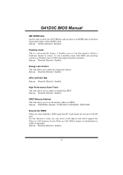
G41D3C BIOS Manual AMI OEMB table Set this function to work, you may need a LAN add-on card which supports the Wake on motherboard to an OEMB table in headless mode, both BIOS and operating system (e.g. Options: FED00000h (Default) / FED01000h / FED02000h / FED03000h Resume On PME# When you to set ...
G41D3C BIOS Manual AMI OEMB table Set this function to work, you may need a LAN add-on card which supports the Wake on motherboard to an OEMB table in headless mode, both BIOS and operating system (e.g. Options: FED00000h (Default) / FED01000h / FED02000h / FED03000h Resume On PME# When you to set ...


