
Setup Manual
Page 2
Table of Contents Chapter 1: Introduction 3 1.1 Before You Start 3 1.2 Package Checklist 3 1.3 Motherboard Features 4 1.4 Rear Panel Connectors 6 1.5 Motherboard Layout 7 Chapter 2: Hardware Installation 8 2.1 Installing Central Processing Unit (CPU 8 2.2 FAN Headers 10 2.3 Installing System Memory 11 2.4 Connectors and Slots 13 Chapter 3: Headers & Jumpers Setup 15 3.1 ...
Table of Contents Chapter 1: Introduction 3 1.1 Before You Start 3 1.2 Package Checklist 3 1.3 Motherboard Features 4 1.4 Rear Panel Connectors 6 1.5 Motherboard Layout 7 Chapter 2: Hardware Installation 8 2.1 Installing Central Processing Unit (CPU 8 2.2 FAN Headers 10 2.3 Installing System Memory 11 2.4 Connectors and Slots 13 Chapter 3: Headers & Jumpers Setup 15 3.1 ...
Setup Manual
Page 3
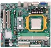
...Cable X 1 (optional) USB 2.0 Cable X1 (optional) S/PDIF out Cable X 1 (optional) 3 CHAPTER 1: INTRODUCTION TA690G AM2 1.1 BEFORE YOU START Thank you take the motherboard out from anti-static bag, ground yourself properly by touching any safely grounded appliance, or use grounded wrist strap to remove the static charge. „...bend or flex the board. „ Do not leave any unfastened small parts inside the case after installation. Hold the board on motherboard or the rear side of the board unless necessary. Loose parts will cause short circuits which may damage the equipment. „ ...
...Cable X 1 (optional) USB 2.0 Cable X1 (optional) S/PDIF out Cable X 1 (optional) 3 CHAPTER 1: INTRODUCTION TA690G AM2 1.1 BEFORE YOU START Thank you take the motherboard out from anti-static bag, ground yourself properly by touching any safely grounded appliance, or use grounded wrist strap to remove the static charge. „...bend or flex the board. „ Do not leave any unfastened small parts inside the case after installation. Hold the board on motherboard or the rear side of the board unless necessary. Loose parts will cause short circuits which may damage the equipment. „ ...
Setup Manual
Page 4
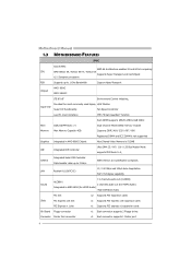
... / 100 / 133 Bus Master Mode supports PIO Mode 0~4, SATA II Integrated Serial ATA Controller Data transfer rates up to 3 Gb/s. SATA Version 2.0 specification compliant. Motherboard Manual 1.3 MOTHERBOARD FEATURES SPEC Socket AM2 AMD 64 Architecture enables 32 and 64 bit computing CPU AMD Athlon 64 / Athlon 64 FX / Athlon 64 Supports Hyper Transport...
... / 100 / 133 Bus Master Mode supports PIO Mode 0~4, SATA II Integrated Serial ATA Controller Data transfer rates up to 3 Gb/s. SATA Version 2.0 specification compliant. Motherboard Manual 1.3 MOTHERBOARD FEATURES SPEC Socket AM2 AMD 64 Architecture enables 32 and 64 bit computing CPU AMD Athlon 64 / Athlon 64 FX / Athlon 64 Supports Hyper Transport...

Setup Manual
Page 6
Motherboard Manual 1.4 REAR PANEL CONNECTORS X PS/2 Mouse Port Y PS/2 Keyboard Port Z S-Video TV-Out Port Transmit analog video signals to TV or any other display panels ...
Motherboard Manual 1.4 REAR PANEL CONNECTORS X PS/2 Mouse Port Y PS/2 Keyboard Port Z S-Video TV-Out Port Transmit analog video signals to TV or any other display panels ...

Setup Manual
Page 7
DVI-D VGA 1.5 MOTHERBOARD LAYOUT JKBMS1 JATXPWR2 JCFAN1 TA690G AM2 JATXPWR1 JTVOUT1 JHDMI DIMMA1 DIMMB1 DIMMA2 DIMMB2 Socket A M2 JUSB1 JUSBLAN1 JNFAN1 AMD 690G IDE1 FDD1 AUDIO1 LAN JAUDIOF1 PEX16_1 Codec PEX1_1 JSPDIF_OUT1 JSPDIF_IN1 JCDIN1 PCI1 BAT1 JCMOS1 AMD SB600 BIOS SATA2 SATA1 Super I/O JPRNT1 PCI2 JCOM1 JUSB2 JUSB3 LED_D1 LED_D2 SATA4 SATA3 JUSB4 JSFAN2 JPANEL1 PWRSW1 JSFAN1 RSTSW1 Note: ■ represents the 1st pin. 7
DVI-D VGA 1.5 MOTHERBOARD LAYOUT JKBMS1 JATXPWR2 JCFAN1 TA690G AM2 JATXPWR1 JTVOUT1 JHDMI DIMMA1 DIMMB1 DIMMA2 DIMMB2 Socket A M2 JUSB1 JUSBLAN1 JNFAN1 AMD 690G IDE1 FDD1 AUDIO1 LAN JAUDIOF1 PEX16_1 Codec PEX1_1 JSPDIF_OUT1 JSPDIF_IN1 JCDIN1 PCI1 BAT1 JCMOS1 AMD SB600 BIOS SATA2 SATA1 Super I/O JPRNT1 PCI2 JCOM1 JUSB2 JUSB3 LED_D1 LED_D2 SATA4 SATA3 JUSB4 JSFAN2 JPANEL1 PWRSW1 JSFAN1 RSTSW1 Note: ■ represents the 1st pin. 7

Setup Manual
Page 8
Motherboard Manual CHAPTER 2: HARDWARE INSTALLATION 2.1 INSTALLING CENTRAL PROCESSING UNIT (CPU) Step 1: Remove the socket protection cap. Step 2: Pull the lever toward direction A from the socket and then raise the lever up to a 90-degree angle. The CPU will fit only in the correct orientation. 8 Step 3: Look for the white triangle on socket, and the gold triangle on CPU should point towards this white triangle.
Motherboard Manual CHAPTER 2: HARDWARE INSTALLATION 2.1 INSTALLING CENTRAL PROCESSING UNIT (CPU) Step 1: Remove the socket protection cap. Step 2: Pull the lever toward direction A from the socket and then raise the lever up to a 90-degree angle. The CPU will fit only in the correct orientation. 8 Step 3: Look for the white triangle on socket, and the gold triangle on CPU should point towards this white triangle.

Setup Manual
Page 10
... to pin#2, and the black wire is Ground and should be different according to GND. 10 The JSFAN1/JSFAN2 and JNFAN1 support 3-pin head connectors. Motherboard Manual 2.2 FAN HEADERS These fan headers support cooling-fans built in the computer. Connect the fan cable to the connector while matching the black wire...
... to pin#2, and the black wire is Ground and should be different according to GND. 10 The JSFAN1/JSFAN2 and JNFAN1 support 3-pin head connectors. Motherboard Manual 2.2 FAN HEADERS These fan headers support cooling-fans built in the computer. Connect the fan cable to the connector while matching the black wire...

Setup Manual
Page 12
... not installed.) The DRAM bus width of the memory module must meet the following requirements: Install memory module of the motherboard, the memory module must be the same (x8 or x16) 12 Motherboard Manual B. Memory Capacity DIMM Socket Location DDR2 Module DIMMA1 256MB/512MB/1024MB DIMMB1 256MB/512MB/1024MB DIMMA2 256MB/512MB...
... not installed.) The DRAM bus width of the memory module must meet the following requirements: Install memory module of the motherboard, the memory module must be the same (x8 or x16) 12 Motherboard Manual B. Memory Capacity DIMM Socket Location DDR2 Module DIMMA1 256MB/512MB/1024MB DIMMB1 256MB/512MB/1024MB DIMMA2 256MB/512MB...
Setup Manual
Page 13
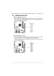
TA690G AM2 2.4 CONNECTORS AND SLOTS FDD1: Floppy Disk Connector The motherboard provides a standard floppy disk connector that provides PIO Mode 0~4, Bus Master, and Ultra DMA 33/66/100/133 functionality. The IDE connector can connect a master and a slave drive, so you can connect up to two hard disk drives. 40 39 21 13 This connector supports the provided floppy drive ribbon cables. 34 33 2 1 IDE1: Hard Disk Connector The motherboard has a 32-bit Enhanced PCI IDE Controller that supports 360K, 720K, 1.2M, 1.44M and 2.88M floppy disk types.
TA690G AM2 2.4 CONNECTORS AND SLOTS FDD1: Floppy Disk Connector The motherboard provides a standard floppy disk connector that provides PIO Mode 0~4, Bus Master, and Ultra DMA 33/66/100/133 functionality. The IDE connector can connect a master and a slave drive, so you can connect up to two hard disk drives. 40 39 21 13 This connector supports the provided floppy drive ribbon cables. 34 33 2 1 IDE1: Hard Disk Connector The motherboard has a 32-bit Enhanced PCI IDE Controller that supports 360K, 720K, 1.2M, 1.44M and 2.88M floppy disk types.

Setup Manual
Page 14
... Slot - Data transfer bandwidth up to 250MB/s per direction, for expansion cards. PCI-Express 1.0a compliant. - PEX16_1 PEX1_1 PCI1~PCI2: Peripheral Component Interconnect Slots This motherboard is a bus standard for an aggregate of 8GB/s totally. PEX1_1: PCI-Express x1 slots - PCI-Express 1.0a compliant. - PCI-Express supports a raw bit-rate of...
... Slot - Data transfer bandwidth up to 250MB/s per direction, for expansion cards. PCI-Express 1.0a compliant. - PEX16_1 PEX1_1 PCI1~PCI2: Peripheral Component Interconnect Slots This motherboard is a bus standard for an aggregate of 8GB/s totally. PEX1_1: PCI-Express x1 slots - PCI-Express 1.0a compliant. - PCI-Express supports a raw bit-rate of...

Setup Manual
Page 16
Motherboard Manual JATXPWR1: ATX Power Source Connector This connector allows user to connect 24-pin power connector on the ATX power supply. 12 24 Pin Assignment ...
Motherboard Manual JATXPWR1: ATX Power Source Connector This connector allows user to connect 24-pin power connector on the ATX power supply. 12 24 Pin Assignment ...

Setup Manual
Page 18
... 3. Power on pin2-3, it allows user to restore the BIOS safe setting and the CMOS data, please carefully follow the procedures to avoid damaging the motherboard. 13 13 Pin 1-2 Close: Normal Operation (default). 13 Pin 2-3 Close: Clear CMOS data. ※ Clear CMOS Procedures: 1. Reset your desired ...password or clear the CMOS data. 18 Wait for five seconds. 4. Set the jumper to "Pin 2-3 close ". 5. Motherboard Manual JCDIN1: CD-ROM Audio-in Connector This connector allows user to connect the audio source from the variaty devices, like CD-ROM, DVD-ROM...
... 3. Power on pin2-3, it allows user to restore the BIOS safe setting and the CMOS data, please carefully follow the procedures to avoid damaging the motherboard. 13 13 Pin 1-2 Close: Normal Operation (default). 13 Pin 2-3 Close: Clear CMOS data. ※ Clear CMOS Procedures: 1. Reset your desired ...password or clear the CMOS data. 18 Wait for five seconds. 4. Set the jumper to "Pin 2-3 close ". 5. Motherboard Manual JCDIN1: CD-ROM Audio-in Connector This connector allows user to connect the audio source from the variaty devices, like CD-ROM, DVD-ROM...
Setup Manual
Page 19
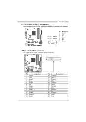
... 7 6 RX+ 7 Ground JPRNT1: Printer Port Connector This header allows you to SATA Controller with 4 channels SATA interface. TA690G AM2 SATA1~SATA4: Serial ATA Connectors The motherboard has a PCI to connector printer on the PC. 2 1 25 Pin Assignment 1 -Strobe 2 -ALF 3 Data 0 4 -Error 5 Data 1 6 -Init 7 Data 2 8 -Scltin 9 Data 3 10 Ground 11 Data 4 12...
... 7 6 RX+ 7 Ground JPRNT1: Printer Port Connector This header allows you to SATA Controller with 4 channels SATA interface. TA690G AM2 SATA1~SATA4: Serial ATA Connectors The motherboard has a PCI to connector printer on the PC. 2 1 25 Pin Assignment 1 -Strobe 2 -ALF 3 Data 0 4 -Error 5 Data 1 6 -Init 7 Data 2 8 -Scltin 9 Data 3 10 Ground 11 Data 4 12...

Setup Manual
Page 20
... detect 2 Received data 3 Transmitted data 1 9 4 Data terminal ready 5 Signal ground 6 Data set ready 7 Request to send 8 Clear to connect the PCI bracket SPDIF input header. Motherboard Manual JSPDIF_OUT1: Digital Audio-out Connector This connector allows user to connect the PCI bracket SPDIF output header. Pin Assignment 1 +5V 2 SPDIF_IN 3 Ground 3 1 JCOM1: Serial...
... detect 2 Received data 3 Transmitted data 1 9 4 Data terminal ready 5 Signal ground 6 Data set ready 7 Request to send 8 Clear to connect the PCI bracket SPDIF input header. Motherboard Manual JSPDIF_OUT1: Digital Audio-out Connector This connector allows user to connect the PCI bracket SPDIF output header. Pin Assignment 1 +5V 2 SPDIF_IN 3 Ground 3 1 JCOM1: Serial...
Setup Manual
Page 21
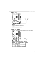
Please refer to show system status. LED_D1 LED_D2 LED_D1 and LED_D2: These 2 LED indicate system power on the motherboard to the table below for different messages: LED_D1 ON ON OFF OFF LED_D2 ON OFF ON OFF Message Normal Memory Error VGA Error Abnormal: CPU / Chipset error. 21 On-Board LED Indicators There are 2 on -board Power Switch button. On-Board Buttons There are 2 LED indicators on diagnostics. TA690G AM2 RSTSW1 PWRSW1 PWRSW1: This is an on-board Reset button. RSTSW1: This is an on -board buttons.
Please refer to show system status. LED_D1 LED_D2 LED_D1 and LED_D2: These 2 LED indicate system power on the motherboard to the table below for different messages: LED_D1 ON ON OFF OFF LED_D2 ON OFF ON OFF Message Normal Memory Error VGA Error Abnormal: CPU / Chipset error. 21 On-Board LED Indicators There are 2 on -board Power Switch button. On-Board Buttons There are 2 LED indicators on diagnostics. TA690G AM2 RSTSW1 PWRSW1 PWRSW1: This is an on-board Reset button. RSTSW1: This is an on -board buttons.

Setup Manual
Page 22
... used in RAID 0 and RAID 1. 4.3 HOW RAID WORKS RAID 0: The controller "stripes" data across multiple drives in parallel. Block 1 Block 3 Block 5 Block 2 Block 4 Block 6 22 Motherboard Manual CHAPTER 4: RAID FUNCTIONS 4.1 OPERATION SYSTEM z Supports Windows XP Home/Professional Edition, and Windows Vista. 4.2 RAID ARRAYS RAID supports the following types of RAID arrays...
... used in RAID 0 and RAID 1. 4.3 HOW RAID WORKS RAID 0: The controller "stripes" data across multiple drives in parallel. Block 1 Block 3 Block 5 Block 2 Block 4 Block 6 22 Motherboard Manual CHAPTER 4: RAID FUNCTIONS 4.1 OPERATION SYSTEM z Supports Windows XP Home/Professional Edition, and Windows Vista. 4.2 RAID ARRAYS RAID supports the following types of RAID arrays...

Setup Manual
Page 24
... 1. - Features and Benefits - Fault Tolerance: Yes. May be stripped using RAID 0 techniques. Resulting in an array, and allows for improved resiliency, performance and rebuild performance. Motherboard Manual RAID 1+0: RAID 1 drives can be simultaneously used with other RAID levels in a RAID 1+0 solution for spare disks. - Block 1 Block 3 Block 5 Block 1 Block 3 Block 5 Block...
... 1. - Features and Benefits - Fault Tolerance: Yes. May be stripped using RAID 0 techniques. Resulting in an array, and allows for improved resiliency, performance and rebuild performance. Motherboard Manual RAID 1+0: RAID 1 drives can be simultaneously used with other RAID levels in a RAID 1+0 solution for spare disks. - Block 1 Block 3 Block 5 Block 1 Block 3 Block 5 Block...

Setup Manual
Page 26
Motherboard Manual 5.2 T-POWER BIOS FEATURE A. Manual Overclock System (M.O.S.) MOS is designed for both Elite and Casual overclockers. It allows users to customize personal overclock settings. 26 Overclocking Navigator Engine (O.N.E.): ONE provides two powerful overclocking engines: MOS and AOS for experienced overclock users.
Motherboard Manual 5.2 T-POWER BIOS FEATURE A. Manual Overclock System (M.O.S.) MOS is designed for both Elite and Casual overclockers. It allows users to customize personal overclock settings. 26 Overclocking Navigator Engine (O.N.E.): ONE provides two powerful overclocking engines: MOS and AOS for experienced overclock users.

Setup Manual
Page 28
provides 3 ideal overclock configurations that are able to increase the system performance, named A.O.S. V8 Tech Engine: This setting will raise about 15%~25% of whole system performance. Based on many tests and experiments, A.O.S. V6 Tech Engine: This setting will raise about 10%~15% of whole system performance. 28 Motherboard Manual Automatic Overclock System (A.O.S.) For beginners in overclock field, BET had developed an easy, fast, and powerful feature to raise the system performance in a single step.
provides 3 ideal overclock configurations that are able to increase the system performance, named A.O.S. V8 Tech Engine: This setting will raise about 15%~25% of whole system performance. Based on many tests and experiments, A.O.S. V6 Tech Engine: This setting will raise about 10%~15% of whole system performance. 28 Motherboard Manual Automatic Overclock System (A.O.S.) For beginners in overclock field, BET had developed an easy, fast, and powerful feature to raise the system performance in a single step.

Setup Manual
Page 30
Memory Integration Test (M.I.T.): This function is "Disabled"; the condition parameter should be changed to "Enable" to complete the test. 30 Motherboard Manual C. MIT allows users to ensure the memory stability. Step 3: When the process is done, change the setting back from CMOS setup and reboot the ...
Memory Integration Test (M.I.T.): This function is "Disabled"; the condition parameter should be changed to "Enable" to complete the test. 30 Motherboard Manual C. MIT allows users to ensure the memory stability. Step 3: When the process is done, change the setting back from CMOS setup and reboot the ...

