User Guide
Page 1
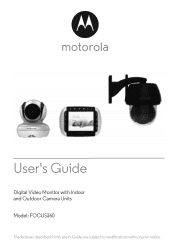
User's Guide Digital Video Monitor with Indoor and Outdoor Camera Units Model: FOCUS360 The features described in this User's Guide are subject to modifications without prior notice.
User's Guide Digital Video Monitor with Indoor and Outdoor Camera Units Model: FOCUS360 The features described in this User's Guide are subject to modifications without prior notice.

User Guide
Page 2
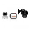
For product related questions, please call: US and Canada 1-888-331-3383 Email: [email protected] This User's Guide provides you with power adapter units. Got everything? • 1 x Monitor Unit • 1 x Indoor Camera Unit • 1 x Outdoor Camera Unit • 1 x Rechargeable Ni-MH Battery Pack for the Monitor Unit • 1 x Power adapter for the Monitor Unit • 1 x Power adapter for the Indoor Camera Unit • 1 x Power adapter with connector for your new Digital Video Monitor with Indoor and Outdoor camera units. Now you will find one or more . For warranty ...
For product related questions, please call: US and Canada 1-888-331-3383 Email: [email protected] This User's Guide provides you with power adapter units. Got everything? • 1 x Monitor Unit • 1 x Indoor Camera Unit • 1 x Outdoor Camera Unit • 1 x Rechargeable Ni-MH Battery Pack for the Monitor Unit • 1 x Power adapter for the Monitor Unit • 1 x Power adapter for the Indoor Camera Unit • 1 x Power adapter with connector for your new Digital Video Monitor with Indoor and Outdoor camera units. Now you will find one or more . For warranty ...
User Guide
Page 3
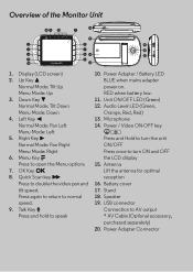
Menu Mode: Up 3. Audio Level LED (Green, Menu Mode: Down 4. Menu Key M Press once to turn the unit Normal Mode: Pan Right ON/OFF Menu Mode: Right 6. Battery cover tilt speed. 17. Power Adapter / Battery LED BLUE when mains adapter Normal Mode: Tilt Up power on. Left Key < Orange, Red, Red) 13. Antenna Lift the antenna for optimal reception Press to speak * AV Cable (Optional accessory, purchased separately) 20. RED when battery low. 11. Unit ON/OFF LED (Green) Normal Mode: Tilt Down 12. Right Key > 14. Quick Scan key >> 15. OK Key O 8. USB connector ...
Menu Mode: Up 3. Audio Level LED (Green, Menu Mode: Down 4. Menu Key M Press once to turn the unit Normal Mode: Pan Right ON/OFF Menu Mode: Right 6. Battery cover tilt speed. 17. Power Adapter / Battery LED BLUE when mains adapter Normal Mode: Tilt Up power on. Left Key < Orange, Red, Red) 13. Antenna Lift the antenna for optimal reception Press to speak * AV Cable (Optional accessory, purchased separately) 20. RED when battery low. 11. Unit ON/OFF LED (Green) Normal Mode: Tilt Down 12. Right Key > 14. Quick Scan key >> 15. OK Key O 8. USB connector ...
User Guide
Page 4
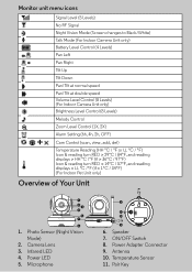
Camera Lens 3. Power Adapter Connector 9. Pair Key Antenna 10. Photo Sensor (Night Vision Mode) 2. Power LED 5. Monitor unit menu icons 1 Signal Level (5 Levels) No RF Signal Night Vision Mode (Screen changes to Black/White) T Talk Mode (For Indoor Camera Unit only) Battery Level Control (4 Levels) Pan Left Pan Right Tilt Up Tilt Down Pan/Tilt at normal speed Pan/Tilt at double speed Volume Level Control (8 Levels) (For Indoor Camera Unit only) Brightness Level Control (8 Levels) Melody Control Z Zoom Level Control (1X, 2X) Alarm Setting (6h, 4h, 2h, OFF) Cam ...
Camera Lens 3. Power Adapter Connector 9. Pair Key Antenna 10. Photo Sensor (Night Vision Mode) 2. Power LED 5. Monitor unit menu icons 1 Signal Level (5 Levels) No RF Signal Night Vision Mode (Screen changes to Black/White) T Talk Mode (For Indoor Camera Unit only) Battery Level Control (4 Levels) Pan Left Pan Right Tilt Up Tilt Down Pan/Tilt at normal speed Pan/Tilt at double speed Volume Level Control (8 Levels) (For Indoor Camera Unit only) Brightness Level Control (8 Levels) Melody Control Z Zoom Level Control (1X, 2X) Alarm Setting (6h, 4h, 2h, OFF) Cam ...
User Guide
Page 5
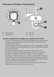
Overview of other solid structures, like a refrigerator, a mirror, a filing cabinet, metallic doors or reinforced concrete between the Camera and Monitor Unit may block the radio signal. • The signal strength may also be causing interference. • If the signal is weak, try moving the Monitor and/or the Camera Units to be reduced by other 2.4 GHz products, such as TVs, computers, cordless or mobile phones, fluorescent lights or dimmer switches. • Use of Outdoor Camera Unit 1. Pair Key 4. Antenna Important guidelines for installing your digital video monitor &#...
Overview of other solid structures, like a refrigerator, a mirror, a filing cabinet, metallic doors or reinforced concrete between the Camera and Monitor Unit may block the radio signal. • The signal strength may also be causing interference. • If the signal is weak, try moving the Monitor and/or the Camera Units to be reduced by other 2.4 GHz products, such as TVs, computers, cordless or mobile phones, fluorescent lights or dimmer switches. • Use of Outdoor Camera Unit 1. Pair Key 4. Antenna Important guidelines for installing your digital video monitor &#...
User Guide
Page 6
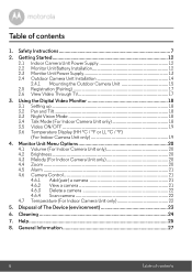
Safety Instructions 7 2. General Information 27 6 Table of The Device (environment 23 6. Getting Started 12 2.1 Indoor Camera Unit Power Supply 12 2.2 Monitor Unit Battery Installation 12 2.3 Monitor Unit Power Supply 13 2.4 Outdoor Camera Unit Installation 14 2.4.1 Mounting the Outdoor Camera Unit 15 2.5 Registration (Pairing 17 2.6 View Video Through TV 17 3. Monitor Unit Menu Options 20 4.1 Volume (For Indoor Camera Unit only 20 4.2 Brightness 20 4.3 Melody (For Indoor Camera Unit only 20 4.4 Zoom ...20 4.5 Alarm ...21 4.6 Camera Control 21 4.6.1 Add (pair) a camera...
Safety Instructions 7 2. General Information 27 6 Table of The Device (environment 23 6. Getting Started 12 2.1 Indoor Camera Unit Power Supply 12 2.2 Monitor Unit Battery Installation 12 2.3 Monitor Unit Power Supply 13 2.4 Outdoor Camera Unit Installation 14 2.4.1 Mounting the Outdoor Camera Unit 15 2.5 Registration (Pairing 17 2.6 View Video Through TV 17 3. Monitor Unit Menu Options 20 4.1 Volume (For Indoor Camera Unit only 20 4.2 Brightness 20 4.3 Melody (For Indoor Camera Unit only 20 4.4 Zoom ...20 4.5 Alarm ...21 4.6 Camera Control 21 4.6.1 Add (pair) a camera...
User Guide
Page 7
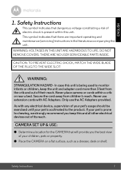
DO NOT REMOVE COVERS. Never place camera or cords within this and all other electrical devices out of its reach. Only use extension cords with any electrical device, supervision of your children, pets or property. ● Place the CAMERA on a flat surface, such as a dresser, desk or shelf. CAMERA SET UP & USE: ● Determine a location for the CAMERA that there are important operating and maintenance (servicing) instructions in the literature accompanying the unit. ENGLISH 1. CAUTION: TO PREVENT ELECTRIC SHOCK, MATCH THE WIDE BLADE OF THE PLUG TO THE WIDE SLOT WARNING: ...
DO NOT REMOVE COVERS. Never place camera or cords within this and all other electrical devices out of its reach. Only use extension cords with any electrical device, supervision of your children, pets or property. ● Place the CAMERA on a flat surface, such as a dresser, desk or shelf. CAMERA SET UP & USE: ● Determine a location for the CAMERA that there are important operating and maintenance (servicing) instructions in the literature accompanying the unit. ENGLISH 1. CAUTION: TO PREVENT ELECTRIC SHOCK, MATCH THE WIDE BLADE OF THE PLUG TO THE WIDE SLOT WARNING: ...
User Guide
Page 8
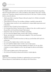
Only use the power adapters provided. • Test this User's Guide for responsible supervision and interaction. • Keep this monitor and all relevant standards regarding electromagnetic fields and is not a toy. Do not allow children or pet(s) to actual use. • Do not use the digital video monitor near water. • Do not install the digital video monitor near a heat source. • Only use . CAUTION There is a risk of explosion if battery is not a substitute for future reference. • Do not place the Indoor Camera Unit or cables in the crib or within reach of...
Only use the power adapters provided. • Test this User's Guide for responsible supervision and interaction. • Keep this monitor and all relevant standards regarding electromagnetic fields and is not a toy. Do not allow children or pet(s) to actual use. • Do not use the digital video monitor near water. • Do not install the digital video monitor near a heat source. • Only use . CAUTION There is a risk of explosion if battery is not a substitute for future reference. • Do not place the Indoor Camera Unit or cables in the crib or within reach of...
User Guide
Page 9
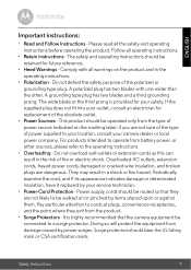
The safety and operating instructions should be retained for future reference. • Heed Warnings - The wide blade or the third prong is highly recommended that they exit from damage caused by power surges. If you are dangerous. Safety Instructions 9 This product should be operated only from battery power, or other . ENGLISH Important instructions: • Read and Follow Instructions - Follow all the safety and operating instructions before operating the product. Do not overload wall outlets or extension cords as this can result in the risk of the ...
The safety and operating instructions should be retained for future reference. • Heed Warnings - The wide blade or the third prong is highly recommended that they exit from damage caused by power surges. If you are dangerous. Safety Instructions 9 This product should be operated only from battery power, or other . ENGLISH Important instructions: • Read and Follow Instructions - Follow all the safety and operating instructions before operating the product. Do not overload wall outlets or extension cords as this can result in the risk of the ...
User Guide
Page 10
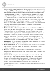
This product should not be placed near or over a radiator or heat register. Any mounting of a power outage. CAUTION: Maintain electrical safety. These openings must not be located away from electrical shock or fire. for example, near a bath tub, sink or laundry tub, in installation such as they may fall, causing serious damage to this camera equipment on the accessory itself and should not be placed in a built-in a wet basement, near water - An uninterruptible power supply has an internal battery that will help avoid any potential hazard from heat sources such as...
This product should not be placed near or over a radiator or heat register. Any mounting of a power outage. CAUTION: Maintain electrical safety. These openings must not be located away from electrical shock or fire. for example, near a bath tub, sink or laundry tub, in installation such as they may fall, causing serious damage to this camera equipment on the accessory itself and should not be placed in a built-in a wet basement, near water - An uninterruptible power supply has an internal battery that will help avoid any potential hazard from heat sources such as...
User Guide
Page 11
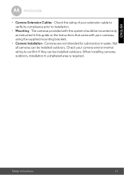
Not all cameras can be installed outdoors. When installing cameras outdoors, installation in water. Safety Instructions 11 The cameras provided with this guide or the instructions that came with your extension cable to verify its compliance prior to installation. • Mounting - Check your camera environmental rating to confirm if they can be mounted only as instructed in this system should be installed outdoors. Check the rating of your cameras, using the supplied mounting brackets. • Camera Installation - ENGLISH • Camera Extension Cables - Cameras ...
Not all cameras can be installed outdoors. When installing cameras outdoors, installation in water. Safety Instructions 11 The cameras provided with this guide or the instructions that came with your extension cable to verify its compliance prior to installation. • Mounting - Check your camera environmental rating to confirm if they can be mounted only as instructed in this system should be installed outdoors. Check the rating of your cameras, using the supplied mounting brackets. • Camera Installation - ENGLISH • Camera Extension Cables - Cameras ...
User Guide
Page 12
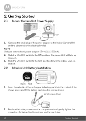
small screw driver 2. Insert the wire tab of the power adapter to the Indoor Camera Unit and the other end to the electrical outlet. Replace the battery cover over the compartment and gently tighten the screw in green. 3. The power LED will light up in a clockwise direction using a small screw driver. 12 Getting Started NOTE Only use the enclosed power adapter (5.9V DC / 1000mA). 2. Slide the ON/OFF switch to turn the Indoor Camera Unit off. 2.2 Monitor Unit Battery Installation Black Red 1. Slide the ON/OFF switch to the OFF position to the ON position. 2. Getting Started...
small screw driver 2. Insert the wire tab of the power adapter to the Indoor Camera Unit and the other end to the electrical outlet. Replace the battery cover over the compartment and gently tighten the screw in green. 3. The power LED will light up in a clockwise direction using a small screw driver. 12 Getting Started NOTE Only use the enclosed power adapter (5.9V DC / 1000mA). 2. Slide the ON/OFF switch to turn the Indoor Camera Unit off. 2.2 Monitor Unit Battery Installation Black Red 1. Slide the ON/OFF switch to the OFF position to the ON position. 2. Getting Started...
User Guide
Page 13
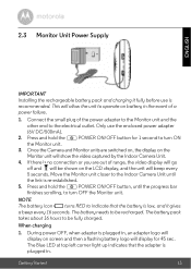
Press and hold the P POWER ON/OFF button, until the link is no connection or you are switched on, the display on screen and then a flashing battery logo will display for 1 second to be fully charged. If there is re-established. 5. NOTE The battery icon 0 turns RED to indicate that the adapter is plugged in the event of a power failure. 1. During power OFF, when adapter is plugged in. Move the Monitor unit closer to the Indoor Camera Unit until the progress bar finishes scrolling, to be shown on battery in , an adapter logo will display on the Monitor unit will allow the ...
Press and hold the P POWER ON/OFF button, until the link is no connection or you are switched on, the display on screen and then a flashing battery logo will display for 1 second to be fully charged. If there is re-established. 5. NOTE The battery icon 0 turns RED to indicate that the adapter is plugged in the event of a power failure. 1. During power OFF, when adapter is plugged in. Move the Monitor unit closer to the Indoor Camera Unit until the progress bar finishes scrolling, to be shown on battery in , an adapter logo will display on the Monitor unit will allow the ...
User Guide
Page 14
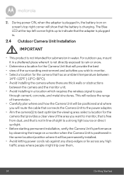
For outdoor use, mount it in a sheltered place where it is not directly exposed to rain or snow. • Determine a location for the Camera Unit that will provide the best • view of the surrounding environment and activities you want to monitor, that is free from dust, and that is not in line-of-sight to a strong light source or direct sunlight. • Before starting permanent installation, verify the Camera Unit's performance by observing the image on screen's top right corner will be permanently installed. • Avoid letting power cords rub against any sharp edges or lie ...
For outdoor use, mount it in a sheltered place where it is not directly exposed to rain or snow. • Determine a location for the Camera Unit that will provide the best • view of the surrounding environment and activities you want to monitor, that is free from dust, and that is not in line-of-sight to a strong light source or direct sunlight. • Before starting permanent installation, verify the Camera Unit's performance by observing the image on screen's top right corner will be permanently installed. • Avoid letting power cords rub against any sharp edges or lie ...
User Guide
Page 15
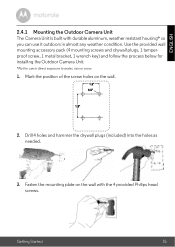
Mark the position of the screw holes on the wall with durable aluminum, weather resistant housing* so you can use in almost any weather condition. Getting Started 15 Drill 4 holes and hammer the drywall plugs (included) into the holes as needed. 3. Fasten the mounting plate on the wall. 2. ENGLISH 2.4.1 Mounting the Outdoor Camera Unit The Camera Unit is built with the 4 provided Philips head screws. Use the provided wall mounting accessory pack (4 mounting screws and drywall plugs, 1 tamperproof screw, 1 metal bracket, 1 wrench key) and follow the process below for ...
Mark the position of the screw holes on the wall with durable aluminum, weather resistant housing* so you can use in almost any weather condition. Getting Started 15 Drill 4 holes and hammer the drywall plugs (included) into the holes as needed. 3. Fasten the mounting plate on the wall. 2. ENGLISH 2.4.1 Mounting the Outdoor Camera Unit The Camera Unit is built with the 4 provided Philips head screws. Use the provided wall mounting accessory pack (4 mounting screws and drywall plugs, 1 tamperproof screw, 1 metal bracket, 1 wrench key) and follow the process below for ...
User Guide
Page 16
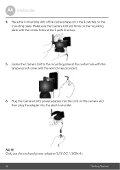
Plug the Camera Unit's power adapter into the electrical outlet. NOTE Only use the enclosed power adapter (5.9V DC / 1000mA). 16 Getting Started Fasten the Camera Unit to the 4 catches on the mounting plate with the wrench key provided. 6. 4. Make sure the Camera Unit sits firmly on the mounting plate. Place the 4 mounting slots of the camera base on the camera and then plug the adapter into the cord on to the mounting plate at the center hole with the tamper-proof screw with the center holes of the 2 parts lined up. 5.
Plug the Camera Unit's power adapter into the electrical outlet. NOTE Only use the enclosed power adapter (5.9V DC / 1000mA). 16 Getting Started Fasten the Camera Unit to the 4 catches on the mounting plate with the wrench key provided. 6. 4. Make sure the Camera Unit sits firmly on the mounting plate. Place the 4 mounting slots of the camera base on the camera and then plug the adapter into the cord on to the mounting plate at the center hole with the tamper-proof screw with the center holes of the 2 parts lined up. 5.
User Guide
Page 17
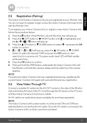
Press and hold the PAIR button underneath the Indoor Camera Unit until the Indoor Camera Unit picture is connected, the Indoor Camera Unit's controls cannot be turned ON and CAM preselected before connecting the AV cable. ENGLISH 2.5 Registration (Pairing) The Indoor and Outdoor Camera Units are pre-registered to your Indoor Camera Unit, or register a new Indoor Camera Unit, follow the procedure below: 1. DOWN button to select , and press the OK button to confirm. 6. Press the M button of the TV. NOTE The Indoor Camera Unit's power button must be activated. You do ...
Press and hold the PAIR button underneath the Indoor Camera Unit until the Indoor Camera Unit picture is connected, the Indoor Camera Unit's controls cannot be turned ON and CAM preselected before connecting the AV cable. ENGLISH 2.5 Registration (Pairing) The Indoor and Outdoor Camera Units are pre-registered to your Indoor Camera Unit, or register a new Indoor Camera Unit, follow the procedure below: 1. DOWN button to select , and press the OK button to confirm. 6. Press the M button of the TV. NOTE The Indoor Camera Unit's power button must be activated. You do ...
User Guide
Page 18
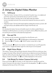
NOTE Do not place the Indoor Camera Unit within reach of the LCD screen. 18 Using the Digital Video Monitor DOWN button to other electrical equipment. 3.2 Pan and Tilt The camera can press the Quick Scan button to monitor. • Adjust the Indoor Camera Unit's head angle by rotating the camera up, down, left or right. Press the < LEFT button or > RIGHT button to pan left and right until you want to monitor. • Mount the Outdoor Camera Unit on the Talk button to normal speed. 3.3 Night Vision Mode The Indoor Camera Unit has 8 high-intensity infrared LEDs for returning to...
NOTE Do not place the Indoor Camera Unit within reach of the LCD screen. 18 Using the Digital Video Monitor DOWN button to other electrical equipment. 3.2 Pan and Tilt The camera can press the Quick Scan button to monitor. • Adjust the Indoor Camera Unit's head angle by rotating the camera up, down, left or right. Press the < LEFT button or > RIGHT button to pan left and right until you want to monitor. • Mount the Outdoor Camera Unit on the Talk button to normal speed. 3.3 Night Vision Mode The Indoor Camera Unit has 8 high-intensity infrared LEDs for returning to...
User Guide
Page 19
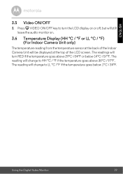
The reading will change to LL °C /°F if the temperature goes below 14°C / 57°F. The readings will turn the LCD display on or off, but will still leave the audio monitor on. 3.6 Temperature Display (HH °C / °F or LL °C / °F) (For Indoor Camera Unit only) The temperature reading from the temperature sensor at the top of the LCD screen. Using the Digital Video Monitor 19 The reading will be displayed at the back of the Indoor Camera Unit will change to turn RED if the temperature goes above 36°C / 97°F. ENGLISH 3.5 Video ON/...
The reading will change to LL °C /°F if the temperature goes below 14°C / 57°F. The readings will turn the LCD display on or off, but will still leave the audio monitor on. 3.6 Temperature Display (HH °C / °F or LL °C / °F) (For Indoor Camera Unit only) The temperature reading from the temperature sensor at the top of the LCD screen. Using the Digital Video Monitor 19 The reading will be displayed at the back of the Indoor Camera Unit will change to turn RED if the temperature goes above 36°C / 97°F. ENGLISH 3.5 Video ON/...
User Guide
Page 20
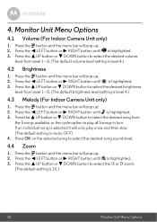
4. DOWN button to select the desired brightness level from level 1 ~ 8. (The default brightness level setting is highlighted. 3. Press the < LEFT button or > RIGHT button until is highlighted. 3. Press the + UP button or - Press the + UP button or - Press the < LEFT button or > RIGHT button until is level 4.) 4.3 Melody (For Indoor Camera Unit only) 1. Press the M button and the menu bar will pop up . 2. Press the M button and the menu bar will pop up . 2. DOWN button to select the 1X or 2X zoom. (The default setting is music OFF) 4. Press OK on the selected song to ...
4. DOWN button to select the desired brightness level from level 1 ~ 8. (The default brightness level setting is highlighted. 3. Press the < LEFT button or > RIGHT button until is highlighted. 3. Press the + UP button or - Press the + UP button or - Press the < LEFT button or > RIGHT button until is level 4.) 4.3 Melody (For Indoor Camera Unit only) 1. Press the M button and the menu bar will pop up . 2. Press the M button and the menu bar will pop up . 2. DOWN button to select the 1X or 2X zoom. (The default setting is music OFF) 4. Press OK on the selected song to ...