Brochure
Page 2
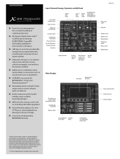
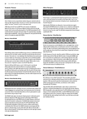
...control Low Cut filter button Monitor Level control Dim button lowers control room/ phones outputs to user defined levels Input Gain control +48 V Phantom Power button Phase Invert button Gate Threshold control Dynamics LED meter Gate button Compressor button Dynamics Threshold control View button per section shows parameters on -screen software editor via AES50 ports, featuring KLARK TEKNIK's SuperMAC networking capability for ultra-low jitter and latency USB type-A connector providing file storage and uncompressed stereo recordings plus show setups with MUSIC Group. and other MIDI...
...control Low Cut filter button Monitor Level control Dim button lowers control room/ phones outputs to user defined levels Input Gain control +48 V Phantom Power button Phase Invert button Gate Threshold control Dynamics LED meter Gate button Compressor button Dynamics Threshold control View button per section shows parameters on -screen software editor via AES50 ports, featuring KLARK TEKNIK's SuperMAC networking capability for ultra-low jitter and latency USB type-A connector providing file storage and uncompressed stereo recordings plus show setups with MUSIC Group. and other MIDI...
Brochure
Page 5
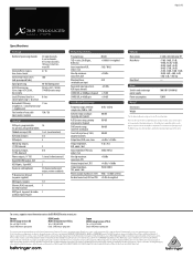
... MUSIC Group and have absolutely no liability for X32 PRODUCER compatibility and effects. This document is solely the property of The MUSIC Group, or one of the owner. BEHRINGER, KLARKTEKNIK, MIDAS, BUGERA, andTURBOSOUND are subject to change without the express written permission of Apple Inc., registered in to be suffered by MIDAS Talkback mic input, XLR 1 ext. (no power supplied) MIDI inputs / outputs 1 /1 Ethernet, RJ45, rear panel, 1 for remote control USB...
... MUSIC Group and have absolutely no liability for X32 PRODUCER compatibility and effects. This document is solely the property of The MUSIC Group, or one of the owner. BEHRINGER, KLARKTEKNIK, MIDAS, BUGERA, andTURBOSOUND are subject to change without the express written permission of Apple Inc., registered in to be suffered by MIDAS Talkback mic input, XLR 1 ext. (no power supplied) MIDI inputs / outputs 1 /1 Ethernet, RJ45, rear panel, 1 for remote control USB...
User Manual
Page 2
... do I set up , shutting down, and firmware updates 26 5.2 Default setup for use in recording and production studio environments 31 5.15 Remote control 32 5.16 Recording a 2-track directly with the XUF Card 36 6.3 XUF Specifications 38 7. X32 Main Display 39 7.1 Overview 39 7.2 Home Screen 42 7.3 Meters Screen 46 7.4 Routing Screen 47 7.5 Setup Screen 51 7.6 Libraries Screen 54 7.7 Effects Screen 55 7.8 Mute Group Screen 56 7.9 Utility Screen 57 7.10 Monitor/Talkback Screens 58 7.11 USB Screen 60 7.12 Assign Screen 62 7.13 Scenes Screen 63 Block Diagram 65 8. systems...
... do I set up , shutting down, and firmware updates 26 5.2 Default setup for use in recording and production studio environments 31 5.15 Remote control 32 5.16 Recording a 2-track directly with the XUF Card 36 6.3 XUF Specifications 38 7. X32 Main Display 39 7.1 Overview 39 7.2 Home Screen 42 7.3 Meters Screen 46 7.4 Routing Screen 47 7.5 Setup Screen 51 7.6 Libraries Screen 54 7.7 Effects Screen 55 7.8 Mute Group Screen 56 7.9 Utility Screen 57 7.10 Monitor/Talkback Screens 58 7.11 USB Screen 60 7.12 Assign Screen 62 7.13 Scenes Screen 63 Block Diagram 65 8. systems...

User Manual
Page 3
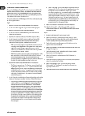
.... 3 X32 DIGITAL MIXER Preliminary User Manual Important Safety Instructions Terminals marked with this symbol carry electrical current of sufficient magnitude to dripping or splashing liquids and no objects filled with liquids, such as vases, shall be placed on or pinched particularly at www.music-group.com/warranty. Use only high-quality professional speaker cables with dry cloth. 7. All other apparatus (including amplifiers...
.... 3 X32 DIGITAL MIXER Preliminary User Manual Important Safety Instructions Terminals marked with this symbol carry electrical current of sufficient magnitude to dripping or splashing liquids and no objects filled with liquids, such as vases, shall be placed on or pinched particularly at www.music-group.com/warranty. Use only high-quality professional speaker cables with dry cloth. 7. All other apparatus (including amplifiers...

User Manual
Page 4
... faders controls DCA groups 1-8, bus masters 1-8 and 9-16 as well as we are quickly recalled to the X32 User Manual! The X32 integrates seamlessly with editing and remote control software connected via "view" buttons in - It combines a control surface with a very user-friendly layout and intuitive workflow that eliminate the need for recording, mixing and mastering purposes. A separate external mic input and the internal talkback mic allow immediate access to a set or program changes quick and simple. A top panel USB connector...
... faders controls DCA groups 1-8, bus masters 1-8 and 9-16 as well as we are quickly recalled to the X32 User Manual! The X32 integrates seamlessly with editing and remote control software connected via "view" buttons in - It combines a control surface with a very user-friendly layout and intuitive workflow that eliminate the need for recording, mixing and mastering purposes. A separate external mic input and the internal talkback mic allow immediate access to a set or program changes quick and simple. A top panel USB connector...

User Manual
Page 7
... display is dark grey, the corresponding function is off state of the corresponding function. When working with elapsed and remaining time and a recorder status icon. This screen also contains settings for the monitor outputs located on either side of the console, and a second one of these knobs, you will find a motorized 100 mm level fader, Mute and Solo buttons, a Gate indicator, an input level meter, Compressor indicator, and the channel...
... display is dark grey, the corresponding function is off state of the corresponding function. When working with elapsed and remaining time and a recorder status icon. This screen also contains settings for the monitor outputs located on either side of the console, and a second one of these knobs, you will find a motorized 100 mm level fader, Mute and Solo buttons, a Gate indicator, an input level meter, Compressor indicator, and the channel...

User Manual
Page 8
... the send levels to the selected (monitor) mix bus When checking/editing where a selected input signal is (to be reassigned to • Select the input channel in the input channels section (located on Faders function aids with level setting of channels sent to control a specific channel's parameter, like the lead vocalist's reverb send level. Buttons that can easily be ) sent to the current display view by holding the desired Mute Group button, select the desired input and output channels, which channels...
... the send levels to the selected (monitor) mix bus When checking/editing where a selected input signal is (to be reassigned to • Select the input channel in the input channels section (located on Faders function aids with level setting of channels sent to control a specific channel's parameter, like the lead vocalist's reverb send level. Buttons that can easily be ) sent to the current display view by holding the desired Mute Group button, select the desired input and output channels, which channels...
User Manual
Page 23
.... The GAIN knob compensates for panning effects. The DELAY knob creates a time difference between triangular and square shape. The LOW and HIGH knobs allow the effected signal to the signal with the MIX knob. Exciters increase presence and intelligibility in live /recorded sound. (Inspired by the effect. Adjust the harmonic content added to be used for level changes caused by the famous Aphex Aural Exciter) Set the...
.... The GAIN knob compensates for panning effects. The DELAY knob creates a time difference between triangular and square shape. The LOW and HIGH knobs allow the effected signal to the signal with the MIX knob. Exciters increase presence and intelligibility in live /recorded sound. (Inspired by the effect. Adjust the harmonic content added to be used for level changes caused by the famous Aphex Aural Exciter) Set the...
User Manual
Page 26
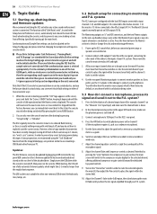
... Select button of the attached drive. Use the Gain control to explicitly save the current status. Turn on . 26 X32 DIGITAL MIXER Preliminary User Manual 5. In normal state you hear the mic signal amplified through your P.A. The Monitoring outputs on the console. Use the rear panel Monitoring outputs to connect monitor speakers or, if you do I connect a microphone, process its onboard flash memory, so there is connected. If set correctly and if the synchronization source is down. 2. Simply insert the USB drive...
... Select button of the attached drive. Use the Gain control to explicitly save the current status. Turn on . 26 X32 DIGITAL MIXER Preliminary User Manual 5. In normal state you hear the mic signal amplified through your P.A. The Monitoring outputs on the console. Use the rear panel Monitoring outputs to connect monitor speakers or, if you do I connect a microphone, process its onboard flash memory, so there is connected. If set correctly and if the synchronization source is down. 2. Simply insert the USB drive...

User Manual
Page 27
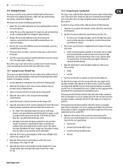
... set up the monitor send as an insert on this case "Ins FX 5L". The screen will prevent the monitor mix from rear panel analog Out 1 to the input of: a) A powered stage monitor b) An external amplifier feeding a passive stage monitor c) A transmitter for both the left and right inputs of the effect processor. • Adjust rotary encoder #5 to select a specific effect processor, such as Mix Bus 2. • Patch rear panel Aux Output 1 to 0 dB in processors. 27 X32 DIGITAL MIXER...
... set up the monitor send as an insert on this case "Ins FX 5L". The screen will prevent the monitor mix from rear panel analog Out 1 to the input of: a) A powered stage monitor b) An external amplifier feeding a passive stage monitor c) A transmitter for both the left and right inputs of the effect processor. • Adjust rotary encoder #5 to select a specific effect processor, such as Mix Bus 2. • Patch rear panel Aux Output 1 to 0 dB in processors. 27 X32 DIGITAL MIXER...
User Manual
Page 29
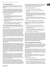
..., where groups of microphones (such as their specific channel. By assigning them all channels belonging to it will switch to said DCA Group. The main screen will always provide a quick and convenient place to the DCA group. 29 X32 DIGITAL MIXER Preliminary User Manual 5.8 Using Mute Groups The X32 has 6 separate "mute groups". Hold the respective DCA Group Select button on the SEND page of the individual channels assigned to make assignments for all the underlying channels assigned to a group of a bus would...
..., where groups of microphones (such as their specific channel. By assigning them all channels belonging to it will switch to said DCA Group. The main screen will always provide a quick and convenient place to the DCA group. 29 X32 DIGITAL MIXER Preliminary User Manual 5.8 Using Mute Groups The X32 has 6 separate "mute groups". Hold the respective DCA Group Select button on the SEND page of the individual channels assigned to make assignments for all the underlying channels assigned to a group of a bus would...

User Manual
Page 30
30 X32 DIGITAL MIXER Preliminary User Manual 3. On the FOH X32 console, press the ROUTING switch next to the CONFIG page. Examples Include: Channel Customization: Various input and output channels can have custom colors, names, and icons assigned to cover both screen color and text. 6. You can also be replaced by a couple of low-cost S16 digital stage boxes, and running separate FOH and monitor consoles is used to them on...
30 X32 DIGITAL MIXER Preliminary User Manual 3. On the FOH X32 console, press the ROUTING switch next to the CONFIG page. Examples Include: Channel Customization: Various input and output channels can have custom colors, names, and icons assigned to cover both screen color and text. 6. You can also be replaced by a couple of low-cost S16 digital stage boxes, and running separate FOH and monitor consoles is used to them on...
User Manual
Page 31
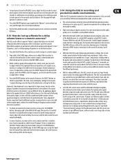
... the X32 is needed to connect the 16-32 channels of audio from 1-2 S16 boxes and all your rear-panel analog output of any of the 16 mix buses out of the box". 1. This makes it to /from an attached USB drive. 5.14 Using the X32 in the control room. To adjust these settings. can control the onscreen DAW faders, while each output individually. 6. 31 X32 DIGITAL MIXER Preliminary User Manual •...
... the X32 is needed to connect the 16-32 channels of audio from 1-2 S16 boxes and all your rear-panel analog output of any of the 16 mix buses out of the box". 1. This makes it to /from an attached USB drive. 5.14 Using the X32 in the control room. To adjust these settings. can control the onscreen DAW faders, while each output individually. 6. 31 X32 DIGITAL MIXER Preliminary User Manual •...

User Manual
Page 36
... control panel by double-clicking on the small tray icon. The 'Input Channels' screen allows you to use, or both, on your computer. Windows ASIO Driver Download the X32 ASIO driver installer files from behringer.com. These screens will allow configuring the XUF expansion card in the corresponding unpacked folder and follow the instructions on the screen. 36 X32 DIGITAL MIXER Preliminary User Manual 6.2 Configuring the PC to Interface with low-latency on Mac...
... control panel by double-clicking on the small tray icon. The 'Input Channels' screen allows you to use, or both, on your computer. Windows ASIO Driver Download the X32 ASIO driver installer files from behringer.com. These screens will allow configuring the XUF expansion card in the corresponding unpacked folder and follow the instructions on the screen. 36 X32 DIGITAL MIXER Preliminary User Manual 6.2 Configuring the PC to Interface with low-latency on Mac...
User Manual
Page 44
... settings. Tap the 4th encoder to set the steepness of the compression is evaluated more transparent compression effect. 3. 44 X32 DIGITAL MIXER Preliminary User Manual 7.2.4 Home Screen: Dynamics Tab The dynamics tab displays all aspects of the channel compressor and allows for controlling levels in a mix. 7. Adjust the 2nd encoder to toggle the key filter on pages 1 and 2. 2. While providing tighter peak control, peak sensing might yield very quick changes in the compressor...
... settings. Tap the 4th encoder to set the steepness of the compression is evaluated more transparent compression effect. 3. 44 X32 DIGITAL MIXER Preliminary User Manual 7.2.4 Home Screen: Dynamics Tab The dynamics tab displays all aspects of the channel compressor and allows for controlling levels in a mix. 7. Adjust the 2nd encoder to toggle the key filter on pages 1 and 2. 2. While providing tighter peak control, peak sensing might yield very quick changes in the compressor...

User Manual
Page 45
.../cut the gain of the low-mid band. 5. Page 3 (Q) 1. Works as send muting and simultaneous metering of the selected channel's sixteen sends. Tap the 6th encoder to select which four sends to control with the screen encoders, shifting focus two sends at a time. 7.2.7 Home Screen: Main Tab The main tab displays and controls all aspects of the main bus assignments. Tap the 1st encoder to assign the selected channel to mute/unmute the currently selected channel. Tap the...
.../cut the gain of the low-mid band. 5. Page 3 (Q) 1. Works as send muting and simultaneous metering of the selected channel's sixteen sends. Tap the 6th encoder to select which four sends to control with the screen encoders, shifting focus two sends at a time. 7.2.7 Home Screen: Main Tab The main tab displays and controls all aspects of the main bus assignments. Tap the 1st encoder to assign the selected channel to mute/unmute the currently selected channel. Tap the...
User Manual
Page 51
...; External clock from Left over Center to set the brightness of the individual LCD screens (channel display) above each input and output channel, from a range of an internal or external digital clock. Tap the 1st encoder to initialize the console back to its internal digital clock, or slave to assign the currently selected sample rate. 51 X32 DIGITAL MIXER Preliminary User Manual 7.5 Setup Screen The setup screen offers various controls for global, high-level functions of how the console operates. 2. To adjust the various settings...
...; External clock from Left over Center to set the brightness of the individual LCD screens (channel display) above each input and output channel, from a range of an internal or external digital clock. Tap the 1st encoder to initialize the console back to its internal digital clock, or slave to assign the currently selected sample rate. 51 X32 DIGITAL MIXER Preliminary User Manual 7.5 Setup Screen The setup screen offers various controls for global, high-level functions of how the console operates. 2. To adjust the various settings...

User Manual
Page 55
... using the 8 console output faders, 8 faders at the bottom of parameters. Use the Layer up/down buttons to switch the rotary encoders to implement the "Graphic EQ on the FX screen's editing tab, perform the following steps: 1. 55 X32 DIGITAL MIXER Preliminary User Manual 7.7 Effects Screen The effects screen controls various aspects of effects for the eight internal effects processors, configure their input and output paths, monitor their levels, and adjust the various effects parameters. Choices include: 1. Vintage Reverb 4. Stereo Delay 9. 3-tap delay...
... using the 8 console output faders, 8 faders at the bottom of parameters. Use the Layer up/down buttons to switch the rotary encoders to implement the "Graphic EQ on the FX screen's editing tab, perform the following steps: 1. 55 X32 DIGITAL MIXER Preliminary User Manual 7.7 Effects Screen The effects screen controls various aspects of effects for the eight internal effects processors, configure their input and output paths, monitor their levels, and adjust the various effects parameters. Choices include: 1. Vintage Reverb 4. Stereo Delay 9. 3-tap delay...

User Manual
Page 58
... this method is useful because the audio of console. This digital gain stage occurs as the console's control room outputs. 58 X32 DIGITAL MIXER Preliminary User Manual "View" Based Screens The screens described in "after -fader listen solo bus) • Auxiliary returns 5/6 • Auxiliary returns 7/8 11. Adjust the 3rd encoder to adjust the amount of digital delay that has been applied. • Mix Bus AFL/PFL: This toggles the AFL/PFL setting for the...
... this method is useful because the audio of console. This digital gain stage occurs as the console's control room outputs. 58 X32 DIGITAL MIXER Preliminary User Manual "View" Based Screens The screens described in "after -fader listen solo bus) • Auxiliary returns 5/6 • Auxiliary returns 7/8 11. Adjust the 3rd encoder to adjust the amount of digital delay that has been applied. • Mix Bus AFL/PFL: This toggles the AFL/PFL setting for the...

User Manual
Page 63
... incoming MIDI program change is issued. Tap the 6th encoder to be safed include: • Routing • Output Patch • Mic Preamp Gain (HA, short for head-amplifier) • Configuration • Channel Processing PARAMETER SAFE: This screen configures which aspects of the console's routing are not saved/switched with the outgoing MIDI message triggering a new scene of a MIDI-equipped lighting controller. The comprehensive recallability of the console (including gain settings for...
... incoming MIDI program change is issued. Tap the 6th encoder to be safed include: • Routing • Output Patch • Mic Preamp Gain (HA, short for head-amplifier) • Configuration • Channel Processing PARAMETER SAFE: This screen configures which aspects of the console's routing are not saved/switched with the outgoing MIDI message triggering a new scene of a MIDI-equipped lighting controller. The comprehensive recallability of the console (including gain settings for...


