User Guide
Page 1
Released 9-15-05. 128-7546 1 of 16 Xpress® Satellite Radio Receiver XMB10 Boom Box User Guide -1-
Released 9-15-05. 128-7546 1 of 16 Xpress® Satellite Radio Receiver XMB10 Boom Box User Guide -1-
User Guide
Page 2
CONTENTS Congratulations 3 FCC Regulations 4 Cautions and Warnings 4 Contents XMB10 5 Installation/Wiring Precautions 5 Setting Up and Installing Your Kit 5 Boom Box XMB10 Controls 5 Interconnect Diagram 9 Positioning the XM Antenna 10 Specifications 12 Maintenance 13 Cleaning the XMB10 Boom Box 13 Troubleshooting 14 Warranty 15 -2- 128-7546 2 of 16
CONTENTS Congratulations 3 FCC Regulations 4 Cautions and Warnings 4 Contents XMB10 5 Installation/Wiring Precautions 5 Setting Up and Installing Your Kit 5 Boom Box XMB10 Controls 5 Interconnect Diagram 9 Positioning the XM Antenna 10 Specifications 12 Maintenance 13 Cleaning the XMB10 Boom Box 13 Troubleshooting 14 Warranty 15 -2- 128-7546 2 of 16

User Guide
Page 3
... reserved. XM® features over 150 digital channels - 100% commercial-free music, over 30 channels of news, sports, talk and entertainment, over 4 million customers. Congratulations Thank you for service sold . XM® is America's #1 Satellite Radio provider with access to Customer Agreement included with an accessory kit, such as the Audiovox Home Kit, Boom Box or Vehicle Kit as required by...
... reserved. XM® features over 150 digital channels - 100% commercial-free music, over 30 channels of news, sports, talk and entertainment, over 4 million customers. Congratulations Thank you for service sold . XM® is America's #1 Satellite Radio provider with access to Customer Agreement included with an accessory kit, such as the Audiovox Home Kit, Boom Box or Vehicle Kit as required by...
User Guide
Page 4
... interference limits relative to a Class B digital device, applicable under Part 15 of any home entertainment component, such as high terrain, trees, overhangs, etc. 4. When installed indoors, unplug the AC Power Adapter from the wall outlet when the XMB10 is not being used for an extended period of time. 6. By adhering to the Receiver Boom Box caused by battery leakage, it could cause harmful...
... interference limits relative to a Class B digital device, applicable under Part 15 of any home entertainment component, such as high terrain, trees, overhangs, etc. 4. When installed indoors, unplug the AC Power Adapter from the wall outlet when the XMB10 is not being used for an extended period of time. 6. By adhering to the Receiver Boom Box caused by battery leakage, it could cause harmful...
User Guide
Page 5
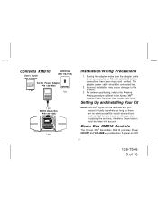
... to an AC wall outlet until all interconnections have been made and verified. Boom Box XMB10 Controls The Xpress XM® Boom Box XMB10 provides Power ON/OFF and VOLUME +/- If using the adapter, make sure the adapter cable is not connected to the Antenna Aiming procedure outlined in the Xpress XM® Satellite Radio Receiver User Guide, 128-7454. pushbuttons. A power-on LED -5- 128-7546 5 of 16 Installation/Wiring Precautions 1. In placing...
... to an AC wall outlet until all interconnections have been made and verified. Boom Box XMB10 Controls The Xpress XM® Boom Box XMB10 provides Power ON/OFF and VOLUME +/- If using the adapter, make sure the adapter cable is not connected to the Antenna Aiming procedure outlined in the Xpress XM® Satellite Radio Receiver User Guide, 128-7454. pushbuttons. A power-on LED -5- 128-7546 5 of 16 Installation/Wiring Precautions 1. In placing...
User Guide
Page 6
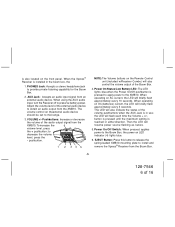
... the Boom Box. 4. Power On/Off Switch: When pressed, applies power to mid-range. 3. EJECT Button: Press this button to release the spring-loaded XMB10 mounting plate to obtain an audio output from the Boom Box. -6- 128-7546 6 of the external audio device to install and remove the Xpress® Receiver from the XMB10. When using the AUX audio input, turn the Receiver off to decrease the volume level, press the - Adjust the volume level of...
... the Boom Box. 4. Power On/Off Switch: When pressed, applies power to mid-range. 3. EJECT Button: Press this button to release the spring-loaded XMB10 mounting plate to obtain an audio output from the Boom Box. -6- 128-7546 6 of the external audio device to install and remove the Xpress® Receiver from the XMB10. When using the AUX audio input, turn the Receiver off to decrease the volume level, press the - Adjust the volume level of...
User Guide
Page 7
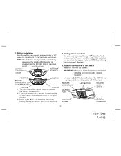
... flip up your Audiovox XMB10 by installing 8 C-Cell batteries as shown; Installing the Receiver in the XMB10 Install the receiver as the Receiver and Boom Box Kit installation are bypassed automatically whenever the supplied AC Adapter is off before installing and removing the Xpress Receiver. RECEIVER COMPARTMENT MOUNTING PLATE EJECT BUTTON MOUNTING PLATE DETENT CONNECTOR GUIDE PIN Xpress RECEIVER CONNECTOR -7- 128-7546 7 of the XMB10; Cabling Interconnections You can operate independently of AC power by following theinterconnect diagram. 3. Press the...
... flip up your Audiovox XMB10 by installing 8 C-Cell batteries as shown; Installing the Receiver in the XMB10 Install the receiver as the Receiver and Boom Box Kit installation are bypassed automatically whenever the supplied AC Adapter is off before installing and removing the Xpress Receiver. RECEIVER COMPARTMENT MOUNTING PLATE EJECT BUTTON MOUNTING PLATE DETENT CONNECTOR GUIDE PIN Xpress RECEIVER CONNECTOR -7- 128-7546 7 of the XMB10; Cabling Interconnections You can operate independently of AC power by following theinterconnect diagram. 3. Press the...

User Guide
Page 8
... lights blue. the receiver will enter the notch on the Xpress to the mounting plate. INSTALLING/REMOVING THE Xpress RECEIVER PUSH IN AT TOP TO SECURE IN PLACE Xpress RECEIVER INSTALLED -8- 128-7546 8 of the Boom Box; If the Receiver does not turn on at the top and pull straight up , gently lower the Xpress into the mounting plate, and press down on the rear...
... lights blue. the receiver will enter the notch on the Xpress to the mounting plate. INSTALLING/REMOVING THE Xpress RECEIVER PUSH IN AT TOP TO SECURE IN PLACE Xpress RECEIVER INSTALLED -8- 128-7546 8 of the Boom Box; If the Receiver does not turn on at the top and pull straight up , gently lower the Xpress into the mounting plate, and press down on the rear...
User Guide
Page 9
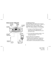
...Installing the Antenna For best reception, the supplied antenna should be left in an open area and as high as possible; When outdoors, the antenna may be placed near a window if in the house or, if outdoors, in its mount atop the Boom Box... 16 HIDE-AWAY ANTENNA CABLE WRAP RECEIVER ANTENNA DC POWER ADAPTER (DC 12V 1.5A) TO AC WALL OUTLET b. Antenna Placement Considerations The antenna should be required to achieve optimum results. Interconnect Diagram RECEIVER BOOM BOX XMB10 ANTENNA JACK (ANT) ANTENNA STORAGE SHELF DC POWER ADAPTER JACK 5. The following guidelines ...
...Installing the Antenna For best reception, the supplied antenna should be left in an open area and as high as possible; When outdoors, the antenna may be placed near a window if in the house or, if outdoors, in its mount atop the Boom Box... 16 HIDE-AWAY ANTENNA CABLE WRAP RECEIVER ANTENNA DC POWER ADAPTER (DC 12V 1.5A) TO AC WALL OUTLET b. Antenna Placement Considerations The antenna should be required to achieve optimum results. Interconnect Diagram RECEIVER BOOM BOX XMB10 ANTENNA JACK (ANT) ANTENNA STORAGE SHELF DC POWER ADAPTER JACK 5. The following guidelines ...
User Guide
Page 10
... described earlier in place on the Boom Box, or remove the antenna from its mount, uncoil the antenna cable, and place it for a terrestrial signal (where available). -10- 128-7546 10 of the XMB10. It has from one of the southeastern sky in this screen, refer to receive XM's signal through standard home walls or a roof. It is not...
... described earlier in place on the Boom Box, or remove the antenna from its mount, uncoil the antenna cable, and place it for a terrestrial signal (where available). -10- 128-7546 10 of the XMB10. It has from one of the southeastern sky in this screen, refer to receive XM's signal through standard home walls or a roof. It is not...
User Guide
Page 11
... the DC adapter cable into the ANT connector on the rear of the Boom Box. b. Make sure you avoid any obstructions that they will work with XM's unique frequency band. Plug the antenna cable into a 110-volt wall receptacle. g When not using battery power as outlined previously in paragraph 3c and obtain an audio output. Plug the other temporary shelter. The cable and connectors used in place atop the XMB10, or remove the...
... the DC adapter cable into the ANT connector on the rear of the Boom Box. b. Make sure you avoid any obstructions that they will work with XM's unique frequency band. Plug the antenna cable into a 110-volt wall receptacle. g When not using battery power as outlined previously in paragraph 3c and obtain an audio output. Plug the other temporary shelter. The cable and connectors used in place atop the XMB10, or remove the...
User Guide
Page 12
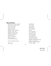
Specifications Nominal Output Power per Channel Total Harmonic Distortion (THD) Frequency Response Signal-to-Noise Ratio Speaker Impedance Headphone Output Impedance Headphone Output Level Headphone Connector Type Auxiliary Input Impedance Auxiliary Input Level Auxiliary Connector Type Equalizer Frequency Overall XMB10 Dimensions Overall AC Adapter Dimensions XMB10 Weight 5.0 Watts Rms 0.3% at 1 Watt 30Hz to 20kHz >65dB Maximum 8 Ohms Nominal 32 Ohms 800 mV (Maximum) 3.5 mm Stereo Jack 8K-Ohms Nominal 2.0 Volts (Maximum) 3.5 mm Stereo Jack -6dB Nominal at 2.5kHz 19.1" W x 7.5" D x 8.43" H 485...
Specifications Nominal Output Power per Channel Total Harmonic Distortion (THD) Frequency Response Signal-to-Noise Ratio Speaker Impedance Headphone Output Impedance Headphone Output Level Headphone Connector Type Auxiliary Input Impedance Auxiliary Input Level Auxiliary Connector Type Equalizer Frequency Overall XMB10 Dimensions Overall AC Adapter Dimensions XMB10 Weight 5.0 Watts Rms 0.3% at 1 Watt 30Hz to 20kHz >65dB Maximum 8 Ohms Nominal 32 Ohms 800 mV (Maximum) 3.5 mm Stereo Jack 8K-Ohms Nominal 2.0 Volts (Maximum) 3.5 mm Stereo Jack -6dB Nominal at 2.5kHz 19.1" W x 7.5" D x 8.43" H 485...

User Guide
Page 13
... overall Boom Box case and speaker grilles for external damage. Maintenance Periodic Inspection The XMB10 Boom Box should be inspected periodically for damage such as nicks, scratches punctures, etc. Check the VOL control for loose, bent or broken pins, misalignment, etc.; Make sure the antenna connector at the rear of any kind and that the AC Adapter plug mates correctly and securely. 5. Inspect the Receiver connector...
... overall Boom Box case and speaker grilles for external damage. Maintenance Periodic Inspection The XMB10 Boom Box should be inspected periodically for damage such as nicks, scratches punctures, etc. Check the VOL control for loose, bent or broken pins, misalignment, etc.; Make sure the antenna connector at the rear of any kind and that the AC Adapter plug mates correctly and securely. 5. Inspect the Receiver connector...
User Guide
Page 14
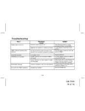
... operate using batteries Intermittent operation ANTENNA error message NO SIGNAL message No sound from XMB10 speakers PROBABLE CAUSE Receiver power is set to off Batteries not installed or installed incorrectly As long as the AC power connector is attached to the rear panel, operation is disabled REMEDY Turn Receiver power on using the Xpress Power On/Off button Install batteries observing correct polarity Remove power connector from rear panel of XMB10 Low battery level Satellite antenna not connected to XMB10 rear panel Xpress Receiver not firmly seated in cradle mounting...
... operate using batteries Intermittent operation ANTENNA error message NO SIGNAL message No sound from XMB10 speakers PROBABLE CAUSE Receiver power is set to off Batteries not installed or installed incorrectly As long as the AC power connector is attached to the rear panel, operation is disabled REMEDY Turn Receiver power on using the Xpress Power On/Off button Install batteries observing correct polarity Remove power connector from rear panel of XMB10 Low battery level Satellite antenna not connected to XMB10 rear panel Xpress Receiver not firmly seated in cradle mounting...
User Guide
Page 15
...incurred for the Company any product or part thereof which vary from the date of original purchase, such defect(s) will be repaired or replaced with the sale of this product. No person or representative is authorized to assume for installation, removal or reinstallation of the product, damage... OR IMPLIED, WHATSOEVER. U.S.A. : AUDIOVOX CORPORATION, 150 MARCUS BLVD., HAUPPAUGE, NEW YORK 11788 z 1-800-645-4994 CANADA : CALL 1-800-645-4994 FOR LOCATION OF WARRANTY STATION SERVING YOUR AREA 1287351 -15- 128-7546 15 of the factory serial number/bar code label(s). ANY ACTION FOR BREACH OF...
...incurred for the Company any product or part thereof which vary from the date of original purchase, such defect(s) will be repaired or replaced with the sale of this product. No person or representative is authorized to assume for installation, removal or reinstallation of the product, damage... OR IMPLIED, WHATSOEVER. U.S.A. : AUDIOVOX CORPORATION, 150 MARCUS BLVD., HAUPPAUGE, NEW YORK 11788 z 1-800-645-4994 CANADA : CALL 1-800-645-4994 FOR LOCATION OF WARRANTY STATION SERVING YOUR AREA 1287351 -15- 128-7546 15 of the factory serial number/bar code label(s). ANY ACTION FOR BREACH OF...
User Guide
Page 16
© 2005 Audiovox Electronics Corporation, 150 Marcus Blvd., Hauppauge, New York 11788 128-7546 -16- 128-7546 16 of 16
© 2005 Audiovox Electronics Corporation, 150 Marcus Blvd., Hauppauge, New York 11788 128-7546 -16- 128-7546 16 of 16


