Installation Manual
Page 1
® SATELLITE DIGITAL AUDIO RECEIVER SYSTEM MODELS SRSIR-001, SRSIR-001FM and MODEL SRSIR-001FMR INSTALLATION MANUAL For Customer Service WWVWisi.taOuudr Wioevbosixte.cAtom Product Information, Photos, FAQ's Owner's Manuals
® SATELLITE DIGITAL AUDIO RECEIVER SYSTEM MODELS SRSIR-001, SRSIR-001FM and MODEL SRSIR-001FMR INSTALLATION MANUAL For Customer Service WWVWisi.taOuudr Wioevbosixte.cAtom Product Information, Photos, FAQ's Owner's Manuals
Installation Manual
Page 2
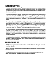
... in conjunction with a satellite RADIO RECEIVER UNIT (RRU), a SATELLITE SYSTEM CONTROL UNIT (SCU) allows the user to select an exact SIRIUS® Radio channel on the easy to read display. This Installation Guide depicts typical installation scenarios. All rights reserved. The Audiovox Electronics SIRIUS® Satellite Digital Audio Control And Receiver System is easily installed using the installation instructions herein, and is designed to work with a 36 month limited warranty (see the back cover of the owner's manual for each of...
... in conjunction with a satellite RADIO RECEIVER UNIT (RRU), a SATELLITE SYSTEM CONTROL UNIT (SCU) allows the user to select an exact SIRIUS® Radio channel on the easy to read display. This Installation Guide depicts typical installation scenarios. All rights reserved. The Audiovox Electronics SIRIUS® Satellite Digital Audio Control And Receiver System is easily installed using the installation instructions herein, and is designed to work with a 36 month limited warranty (see the back cover of the owner's manual for each of...
Installation Manual
Page 3
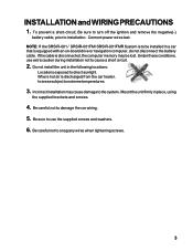
... the following locations: Locations exposed to be lost. Be careful not to damage the car wiring. 5. Connect power wires last. Do not install the unit in place, using the supplied brackets and screws. 4. To prevent a short-circuit, Be sure to turn off the ignition and remove the negative(-) battery cable, prior to use extra caution during installation not to extreme temperatures. 3. Incorrect installation may be installed in a car that...
... the following locations: Locations exposed to be lost. Be careful not to damage the car wiring. 5. Connect power wires last. Do not install the unit in place, using the supplied brackets and screws. 4. To prevent a short-circuit, Be sure to turn off the ignition and remove the negative(-) battery cable, prior to use extra caution during installation not to extreme temperatures. 3. Incorrect installation may be installed in a car that...
Installation Manual
Page 4
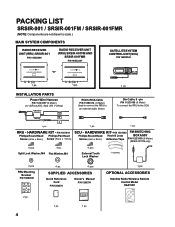
T ER . INSTALLATION PARTS Power Wire Harness P/N 112C3157 (6 Meter) (w/ (2)Fuse,AGC Style 250 V-2Amp) RCA to RCA Cable P/N 112B3114 (6 Meter) Used to connect the RRU to scale.) MAIN SYSTEM COMPONENTS RADIO RECEIVER UNIT (RRU) SRSIR-001 P/N 144D2346 RADIO RECEIVER UNIT (RRU) SRSIR-001FM AND SRSIR-001FMR P/N 144D2347 SATELLITE SYSTEM CONTROL UNIT (SCU) P/N 144D2345 AUDIO OX -or- Din Cable, 6 - P/N 1501442 FM SWITCHING Phillips Round Head Hook & Loop BOX ASSY Screw (4mm x 8mm) Adhesive Tape P/N 112C3159 (6 Meter...
T ER . INSTALLATION PARTS Power Wire Harness P/N 112C3157 (6 Meter) (w/ (2)Fuse,AGC Style 250 V-2Amp) RCA to RCA Cable P/N 112B3114 (6 Meter) Used to connect the RRU to scale.) MAIN SYSTEM COMPONENTS RADIO RECEIVER UNIT (RRU) SRSIR-001 P/N 144D2346 RADIO RECEIVER UNIT (RRU) SRSIR-001FM AND SRSIR-001FMR P/N 144D2347 SATELLITE SYSTEM CONTROL UNIT (SCU) P/N 144D2345 AUDIO OX -or- Din Cable, 6 - P/N 1501442 FM SWITCHING Phillips Round Head Hook & Loop BOX ASSY Screw (4mm x 8mm) Adhesive Tape P/N 112C3159 (6 Meter...
Installation Manual
Page 5
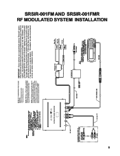
... the cable to avoid any unnecessary re-work. This adaptor can also be purchased at most car stereo installation centers. SAT. AUDIO OUT R L FM OUT TO SCU POWER AUDIO OX 1 2 3 4 5 6 7 8 9 0 SFT Some vehicles use a special dual antenna "Diversity" system. If the vehicle into which this is too small to mate with system) used to connect the RRU Audio Ouput to the Radio Reciever Audio Input. If...
... the cable to avoid any unnecessary re-work. This adaptor can also be purchased at most car stereo installation centers. SAT. AUDIO OUT R L FM OUT TO SCU POWER AUDIO OX 1 2 3 4 5 6 7 8 9 0 SFT Some vehicles use a special dual antenna "Diversity" system. If the vehicle into which this is too small to mate with system) used to connect the RRU Audio Ouput to the Radio Reciever Audio Input. If...

Installation Manual
Page 6
6 AUDIO OX TER. SAT. AUDIO OUT R L TO SCU POWER AUDIO OX 1 2 3 4 5 6 7 8 9 0 SFT
6 AUDIO OX TER. SAT. AUDIO OUT R L TO SCU POWER AUDIO OX 1 2 3 4 5 6 7 8 9 0 SFT
Installation Manual
Page 7
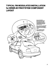
TYPICAL FM MODULATED INSTALLATION for SRSIR-001FM SYSTEM COMPONENT LAYOUT 7
TYPICAL FM MODULATED INSTALLATION for SRSIR-001FM SYSTEM COMPONENT LAYOUT 7
Installation Manual
Page 8
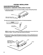
... the mounting location and drill 4x 1/8" (4mm) mounting holes. Cut holes in 4 places Bracket RRU Carpet 8 Mount the unit in 4 places 2. SYSTEM INSTALLATION RADIO RECEIVER UNIT (RRU) PROCEDURE for HORIZONTAL INSTALLATION of the RRU, using 4 Self-tapping Screws (5mm x 15mm), w/Flat Washers and Lock Washers. Attach the mounting brackets to prevent moisture intrusion. WARNING Never mount the unit near the fuel tank. 4x 1/8" (4mm) mounting...
... the mounting location and drill 4x 1/8" (4mm) mounting holes. Cut holes in 4 places Bracket RRU Carpet 8 Mount the unit in 4 places 2. SYSTEM INSTALLATION RADIO RECEIVER UNIT (RRU) PROCEDURE for HORIZONTAL INSTALLATION of the RRU, using 4 Self-tapping Screws (5mm x 15mm), w/Flat Washers and Lock Washers. Attach the mounting brackets to prevent moisture intrusion. WARNING Never mount the unit near the fuel tank. 4x 1/8" (4mm) mounting...
Installation Manual
Page 9
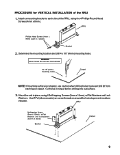
... (silicone sealer) on carpet. RRU Self-tapping Screw (5mm x 15mm), w/Flat Washers and Lockwashers used in 4 places Bracket Carpet 9 Determine the mounting location and drill 4 x 1/8" (4mm) mounting holes. Cut holes in place, using the 4 Phillips Round Head Screws (4mm x 8mm). PROCEDURE for VERTICAL INSTALLATION of the RRU, using 4 Self-tapping Screws (5mm x 15mm), w/Flat Washers and Lock Washers.
... (silicone sealer) on carpet. RRU Self-tapping Screw (5mm x 15mm), w/Flat Washers and Lockwashers used in 4 places Bracket Carpet 9 Determine the mounting location and drill 4 x 1/8" (4mm) mounting holes. Cut holes in place, using the 4 Phillips Round Head Screws (4mm x 8mm). PROCEDURE for VERTICAL INSTALLATION of the RRU, using 4 Self-tapping Screws (5mm x 15mm), w/Flat Washers and Lock Washers.

Installation Manual
Page 10
Determine the mounting location and drill four 4mm mounting holes. Underside of the RRU UNDER THE REAR DECK 1. Rear Deck Self-tapping Screw (5mm x 15mm), w/Flat Washers and Lockwashers used in 4 places 10 PROCEDURE for the MOUNTING of Rear Deck 4x 1/8" (4mm) mounting holes (4 places) 3. Attach the mounting brackets to each side of the RRU, using 4 Self-tapping Screws (5mm x 15mm), w/Flat Washers and Lock Washers. Bracket Phillips Head Screws used in 4 places (4mm x 8mm) 2. Mount the unit in place, using the 4 Phillips Round Head Screws (4mm x 8mm).
Determine the mounting location and drill four 4mm mounting holes. Underside of the RRU UNDER THE REAR DECK 1. Rear Deck Self-tapping Screw (5mm x 15mm), w/Flat Washers and Lockwashers used in 4 places 10 PROCEDURE for the MOUNTING of Rear Deck 4x 1/8" (4mm) mounting holes (4 places) 3. Attach the mounting brackets to each side of the RRU, using 4 Self-tapping Screws (5mm x 15mm), w/Flat Washers and Lock Washers. Bracket Phillips Head Screws used in 4 places (4mm x 8mm) 2. Mount the unit in place, using the 4 Phillips Round Head Screws (4mm x 8mm).
Installation Manual
Page 11
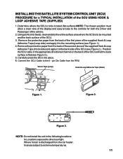
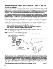
... locations: In Locations exposed to extreme temperatures. 11 NOTE: Do not install the unit in the appropriate directional channel on the back of the supplied Hook & Loop Adhesive Tape (Hook side) and apply it to the mounting surface (see Figure 1.) 4. Where hot air is flat (see Figure 2.). INSTALLING THE SATELLITE SYSTEM CONTROL UNIT (SCU) PROCEDURE for both the Driver and Passenger of the SCU USING HOOK...
... locations: In Locations exposed to extreme temperatures. 11 NOTE: Do not install the unit in the appropriate directional channel on the back of the supplied Hook & Loop Adhesive Tape (Hook side) and apply it to the mounting surface (see Figure 1.) 4. Where hot air is flat (see Figure 2.). INSTALLING THE SATELLITE SYSTEM CONTROL UNIT (SCU) PROCEDURE for both the Driver and Passenger of the SCU USING HOOK...
Installation Manual
Page 12
... be performed. Connect the SCU Cable to the Owner's Manual. © Copyright 2002 Audiovox Electronics Corp. 150 Marcus Blvd. The installation procedure that fuses are functioning, select and listen to over the Hook & Loop type of installation though the Hook & Loop installation (if done correctly) is activated a test of the SCU installation and before the SIRIUS® radio is a secure and sufficient mounting option. pin Din Cable from the car heater. Where...
... be performed. Connect the SCU Cable to the Owner's Manual. © Copyright 2002 Audiovox Electronics Corp. 150 Marcus Blvd. The installation procedure that fuses are functioning, select and listen to over the Hook & Loop type of installation though the Hook & Loop installation (if done correctly) is activated a test of the SCU installation and before the SIRIUS® radio is a secure and sufficient mounting option. pin Din Cable from the car heater. Where...


