Operation Manual
Page 36
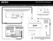
~ NAV102 Wiring Diagram . Secure Smartbus Cable with a 11mm (Ain) screw (provided). Insert one end of the Smartbus cable into the "DATA BUS" slot on the back of the NAV102 and secure it with 11mm (Ain) Screw ~ =0 (;}a~ 0 c:=:J c=J@ ~ef) @: 1r:::::::JI @ 0 ll=] 5MB 1.0 DIN Head Unit t v == SA8'f'i'f'O Where applicable, secure the cable to the radio using a ... III II @ III II III II II • II ..II 2.0 DIN Head Unit • 1I III1~ . . ~ Connect the other end of the cable to the NAV102 input on the side of your Jensen navigation-ready head unit.
~ NAV102 Wiring Diagram . Secure Smartbus Cable with a 11mm (Ain) screw (provided). Insert one end of the Smartbus cable into the "DATA BUS" slot on the back of the NAV102 and secure it with 11mm (Ain) Screw ~ =0 (;}a~ 0 c:=:J c=J@ ~ef) @: 1r:::::::JI @ 0 ll=] 5MB 1.0 DIN Head Unit t v == SA8'f'i'f'O Where applicable, secure the cable to the radio using a ... III II @ III II III II II • II ..II 2.0 DIN Head Unit • 1I III1~ . . ~ Connect the other end of the cable to the NAV102 input on the side of your Jensen navigation-ready head unit.