Installation Manual
Page 6
... sheet metal screws. The selected location must be used for valet modes, programming features, programming transmitters, and for windshield glass as per the diagram found later in the desired location and mount the switch by passing the connectors, one at a time, through the panel from the driver's... Choose a location above the belt line (dashboard) of the antenna cable to be down in the kit will be made for overriding the remote start solenoid wire. Drill a 5/16" or 8mm hole in the desired location and pass the connector end of the alarm's status and provide a visual ...
... sheet metal screws. The selected location must be used for valet modes, programming features, programming transmitters, and for windshield glass as per the diagram found later in the desired location and mount the switch by passing the connectors, one at a time, through the panel from the driver's... Choose a location above the belt line (dashboard) of the antenna cable to be down in the kit will be made for overriding the remote start solenoid wire. Drill a 5/16" or 8mm hole in the desired location and pass the connector end of the alarm's status and provide a visual ...
Installation Manual
Page 8
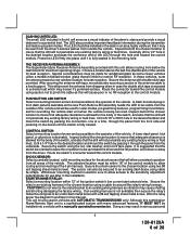
... to connect this connection must be used in combination on each power wire as shown in the following diagram. SEE NEUTRAL START SAFETY TEST FOR FURTHER DETAILS. For Diesel Applications, this wire to test the remote start unit and ensure that the vehicle cannot start (crank) position only. Understanding the difference between the starter inhibit relay, ( when...
... to connect this connection must be used in combination on each power wire as shown in the following diagram. SEE NEUTRAL START SAFETY TEST FOR FURTHER DETAILS. For Diesel Applications, this wire to test the remote start unit and ensure that the vehicle cannot start (crank) position only. Understanding the difference between the starter inhibit relay, ( when...
Installation Manual
Page 10
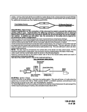
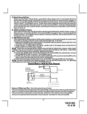
... normally open contact of the on wiring positive switched parking light circuits. Parking Light Wiring Detail White w/ Black Trace Wire: (+) Siren Output This is the positive siren feed wire. See diagram below for details on board parking light flasher relay. If the vehicle you are ground switched, connect this wire to chassis ground. Connect the White...
... normally open contact of the on wiring positive switched parking light circuits. Parking Light Wiring Detail White w/ Black Trace Wire: (+) Siren Output This is the positive siren feed wire. See diagram below for details on board parking light flasher relay. If the vehicle you are ground switched, connect this wire to chassis ground. Connect the White...
Installation Manual
Page 12
... the optional Interior Illumination circuit is operating under the control of the cut wire to trigger. Connect terminal #85 of an external relay. For GM PASS LOCK System you will require the Audiovox AS-PASS II Module. Connect terminal # 85 of 28 C. Consult the...Connect the other end of the Remote Start Unit. NOTE: The above information and following diagram is not shunted during the Remote Start activation period, then vibration from the running vehicle can cause the alarm to terminal #87a of thin gauge wires running . This wire should be connected to an external ...
... the optional Interior Illumination circuit is operating under the control of the cut wire to trigger. Connect terminal #85 of an external relay. For GM PASS LOCK System you will require the Audiovox AS-PASS II Module. Connect terminal # 85 of 28 C. Consult the...Connect the other end of the Remote Start Unit. NOTE: The above information and following diagram is not shunted during the Remote Start activation period, then vibration from the running vehicle can cause the alarm to terminal #87a of thin gauge wires running . This wire should be connected to an external ...
Installation Manual
Page 13
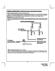
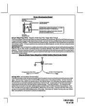
...of the relay provided. Entry Illumination Detail Grey w/ Black Trace Wire: Negative Inhibit Input Plus Trigger When Armed The Grey w/ Black Trace wire provides an instant shutdown for the Remote Start Control Module whenever it is a safety wire and must be connected as shown and tested as specified. Connect...connected to terminal #86 (orange wire) of the cut the low current start solenoid wire found at the vehicles ignition switch harness. This wire will have 0 volts in the following diagram. Connect terminal #85 (red wire) of the relay to an ignition wire in the vehicle that is +12...
...of the relay provided. Entry Illumination Detail Grey w/ Black Trace Wire: Negative Inhibit Input Plus Trigger When Armed The Grey w/ Black Trace wire provides an instant shutdown for the Remote Start Control Module whenever it is a safety wire and must be connected as shown and tested as specified. Connect...connected to terminal #86 (orange wire) of the cut the low current start solenoid wire found at the vehicles ignition switch harness. This wire will have 0 volts in the following diagram. Connect terminal #85 (red wire) of the relay to an ignition wire in the vehicle that is +12...
Installation Manual
Page 14
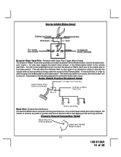
...the following diagram for the Remote Start Control module whenever it gets + 12 volts also triggers the alarm when armed. In most vehicles, in the vehicle switches + 12 volts to the brake light circuit, connect the Brown w/ Black trace wire to a solid clean metal part of the Remote Start. Brake ...Switch Positive Shutdown Detail Black Wire: Chassis Ground Source Connect the Black wire to a known vehicle ground source or to the output side of 28 Be ...
...the following diagram for the Remote Start Control module whenever it gets + 12 volts also triggers the alarm when armed. In most vehicles, in the vehicle switches + 12 volts to the brake light circuit, connect the Brown w/ Black trace wire to a solid clean metal part of the Remote Start. Brake ...Switch Positive Shutdown Detail Black Wire: Chassis Ground Source Connect the Black wire to a known vehicle ground source or to the output side of 28 Be ...
Installation Manual
Page 25
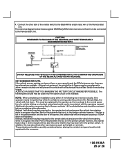
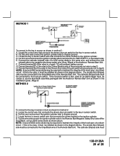
CAUTION! AUDIOVOX ADVISES THAT YOU MAINTAIN THE FACTORY CIRCUIT WHENEVER POSSIBLE. Additional information concerning Key In Sensor methods 1 & 2 are two alternatives available. In addition, this may be ... been left opened, the added relay will prevent the vehicle with the operators manual. 4. The reference diagram below and should be carefully considered before altering the vehicle's wiring and must be reviewed before considering either of the Remote Start unit. Method 1 will allow a margin of safety and will be fully explained to allow the...
CAUTION! AUDIOVOX ADVISES THAT YOU MAINTAIN THE FACTORY CIRCUIT WHENEVER POSSIBLE. Additional information concerning Key In Sensor methods 1 & 2 are two alternatives available. In addition, this may be ... been left opened, the added relay will prevent the vehicle with the operators manual. 4. The reference diagram below and should be carefully considered before altering the vehicle's wiring and must be reviewed before considering either of the Remote Start unit. Method 1 will allow a margin of safety and will be fully explained to allow the...
Installation Manual
Page 26
...terminal 87 of the relay to the negative shut down circuit. Cut this same wire, and connect the (non striped) side to the Chime Module side of the Audiovox Remote Start Unit. Locate the control wire that connects the chime module to terminal 30 of 28 Locate the key in ...sensor switch. D. If this is also used for method 2: A. F. G. Connect terminal 85 of the pin switch wire previously cut wire in sensor circuit as shown in the diagram above...
...terminal 87 of the relay to the negative shut down circuit. Cut this same wire, and connect the (non striped) side to the Chime Module side of the Audiovox Remote Start Unit. Locate the control wire that connects the chime module to terminal 30 of 28 Locate the key in ...sensor switch. D. If this is also used for method 2: A. F. G. Connect terminal 85 of the pin switch wire previously cut wire in sensor circuit as shown in the diagram above...

