Installation Manual
Page 1
... mode as custom code. 1 From APS997 with 07SP transmitters 5/07 Rev A: 136-4002 Updated F/W to add DBI Tach, Module Rev 6. 6-30-08 Model APS-997a Installation Manual SELECTABLE FEATURES The selectable features can either be selected to operate from the valet switch or operate as follows: Turn the ignition on Press...
... mode as custom code. 1 From APS997 with 07SP transmitters 5/07 Rev A: 136-4002 Updated F/W to add DBI Tach, Module Rev 6. 6-30-08 Model APS-997a Installation Manual SELECTABLE FEATURES The selectable features can either be selected to operate from the valet switch or operate as follows: Turn the ignition on Press...
Installation Manual
Page 5
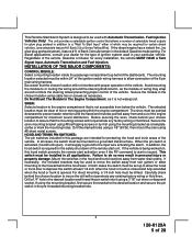
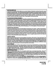
...engine compartment that the chosen location will supply a ground to do so may be used with proper operation of the remote start is not waterproof. This Remote Start/Alarm System is not accessible from below the vehicle. Be certain that is designed to or routing the wiring around...control that the mounting screws will not penetrate any factory wiring or fluid lines. INSTALLATION OF THE MAJOR COMPONENTS: CONTROL MODULE: Select a mounting location inside the passenger compartment (up to a "Wait To Start Input" either of the 6 pin main wiring harness. Secure the module in...
...engine compartment that the chosen location will supply a ground to do so may be used with proper operation of the remote start is not waterproof. This Remote Start/Alarm System is not accessible from below the vehicle. Be certain that is designed to or routing the wiring around...control that the mounting screws will not penetrate any factory wiring or fluid lines. INSTALLATION OF THE MAJOR COMPONENTS: CONTROL MODULE: Select a mounting location inside the passenger compartment (up to a "Wait To Start Input" either of the 6 pin main wiring harness. Secure the module in...
Installation Manual
Page 6
... a location above the belt line (dashboard) of the vehicle for best reception. After securing the antenna with this combination Alarm/Remote Start unit is a sophisticated system with a manually operated transmission. Route the switch's connector toward a rear window location for best reception...vehicle and will be used for valet modes, programming features, programming transmitters, and for overriding the remote start solenoid wire. The LED should be installed into place until the switch is fully seated. THE RECEIVER/ANTENNA ASSEMBLY: The Superheterodyne Receiver Antenna ...
... a location above the belt line (dashboard) of the vehicle for best reception. After securing the antenna with this combination Alarm/Remote Start unit is a sophisticated system with a manually operated transmission. Route the switch's connector toward a rear window location for best reception...vehicle and will be used for valet modes, programming features, programming transmitters, and for overriding the remote start solenoid wire. The LED should be installed into place until the switch is fully seated. THE RECEIVER/ANTENNA ASSEMBLY: The Superheterodyne Receiver Antenna ...
Installation Manual
Page 7
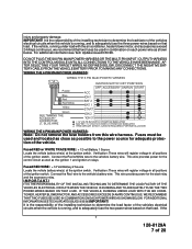
... vehicle battery wire(s) at the ignition switch. It is the responsibility of the installing technician to determine the load factor of the vehicle. If the vehicle, running , and to the power source for the start relay and the accessory relay. DO NOT PLUG THE SIX PIN MAIN POWER HARNESS...TARGET WIRES AS DEFINED BELOW, DISCONNECT THE NEGATIVE BATTERY CABLE FROM THE VEHICLE BATTERY PRIOR TO MAKING ANY CONNECTIONS. It is the responsibility of the installing technician to determine the load factor of 28 WIRING THE 6 PIN MAIN POWER HARNESS: WIRING THE 6 PIN MAIN POWER HARNESS: Note: Do...
... vehicle battery wire(s) at the ignition switch. It is the responsibility of the installing technician to determine the load factor of the vehicle. If the vehicle, running , and to the power source for the start relay and the accessory relay. DO NOT PLUG THE SIX PIN MAIN POWER HARNESS...TARGET WIRES AS DEFINED BELOW, DISCONNECT THE NEGATIVE BATTERY CABLE FROM THE VEHICLE BATTERY PRIOR TO MAKING ANY CONNECTIONS. It is the responsibility of the installing technician to determine the load factor of 28 WIRING THE 6 PIN MAIN POWER HARNESS: WIRING THE 6 PIN MAIN POWER HARNESS: Note: Do...
Installation Manual
Page 8
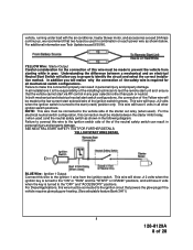
...) 8 128-8129A 8 of the Yellow wire will have +12 volts when the ignition switch is the responsibility of the installing technician to connect this connection must be made to the start solenoid wire of the starter cut relay (when used). In both mechanical and electrical neutral...damage. Failure to test the remote start unit and ensure that the vehicle cannot start via RF control in personal injury and property damage. For the electrical neutral switch configuration, this wire to properly identify the circuit and select the correct installation method. YELLOW Wire: Starter ...
...) 8 128-8129A 8 of the Yellow wire will have +12 volts when the ignition switch is the responsibility of the installing technician to connect this connection must be made to the start solenoid wire of the starter cut relay (when used). In both mechanical and electrical neutral...damage. Failure to test the remote start unit and ensure that the vehicle cannot start via RF control in personal injury and property damage. For the electrical neutral switch configuration, this wire to properly identify the circuit and select the correct installation method. YELLOW Wire: Starter ...
Installation Manual
Page 11
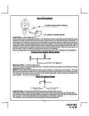
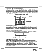
... 28 Hood Pin Switch Detail Light Blue Wire: Ground Output While Running Under Remote Start Control This wire provides a 300mA ground output that becomes active 3 seconds before the Remote Start Unit initializes and remains grounded while running under title "Completing The Installation". When the zone clears, the siren will need to be used to accommodate...
... 28 Hood Pin Switch Detail Light Blue Wire: Ground Output While Running Under Remote Start Control This wire provides a 300mA ground output that becomes active 3 seconds before the Remote Start Unit initializes and remains grounded while running under title "Completing The Installation". When the zone clears, the siren will need to be used to accommodate...
Installation Manual
Page 12
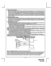
...#86 of a external relay. Connect the previously selected resistor from the resistor pack supplied. 2. For GM PASS LOCK System you will require the Audiovox AS-PASS II Module. If this case, connect the Light Blue Wire to terminal #30. 5. Consult the factory service manual for a minimum of... three ignition outputs to start and keep the vehicle's engine running from the Remote Start Unit to bypass the system while the vehicle is operating under the control of an external relay. GM VATS Key Override: If the vehicle has the General Motors VATS system installed, you will need to...
...#86 of a external relay. Connect the previously selected resistor from the resistor pack supplied. 2. For GM PASS LOCK System you will require the Audiovox AS-PASS II Module. If this case, connect the Light Blue Wire to terminal #30. 5. Consult the factory service manual for a minimum of... three ignition outputs to start and keep the vehicle's engine running from the Remote Start Unit to bypass the system while the vehicle is operating under the control of an external relay. GM VATS Key Override: If the vehicle has the General Motors VATS system installed, you will need to...
Installation Manual
Page 13
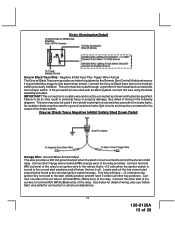
...be used with an alarm system, connect this wire using the diode assembly provided. See below for detail of wiring, also see Yellow Start wire detail for connection to terminal #86 (orange wire) of the brake switch. This wire may result in the vehicle that is...installed. Locate and cut the low current start positions and off when the key is a safety wire and must be connected as shown and tested as specified. Entry Illumination Detail Grey w/ Black Trace Wire: Negative Inhibit Input Plus Trigger When Armed The Grey w/ Black Trace wire provides an instant shutdown for the Remote Start...
...be used with an alarm system, connect this wire using the diode assembly provided. See below for detail of wiring, also see Yellow Start wire detail for connection to terminal #86 (orange wire) of the brake switch. This wire may result in the vehicle that is...installed. Locate and cut the low current start positions and off when the key is a safety wire and must be connected as shown and tested as specified. Entry Illumination Detail Grey w/ Black Trace Wire: Negative Inhibit Input Plus Trigger When Armed The Grey w/ Black Trace wire provides an instant shutdown for the Remote Start...
Installation Manual
Page 15
... two. When the zone clears, the siren will emit three chirps. Pressing the pre-programmed transmitter button for additional information. This Remote Start unit learns the tach rate of the vehicle and in most cases will operate properly from one multi coil pack regardless of the ... or through the firewall into the engine compartment and connect to terminal # 86 of the Remote Start module. See below for vehicles with interior delay lighting see programming under title "Completing The Installation". Connect the Dark Blue wire to the negative side of 28 Green w/ Orange Trace Wire...
... two. When the zone clears, the siren will emit three chirps. Pressing the pre-programmed transmitter button for additional information. This Remote Start unit learns the tach rate of the vehicle and in most cases will operate properly from one multi coil pack regardless of the ... or through the firewall into the engine compartment and connect to terminal # 86 of the Remote Start module. See below for vehicles with interior delay lighting see programming under title "Completing The Installation". Connect the Dark Blue wire to the negative side of 28 Green w/ Orange Trace Wire...
Installation Manual
Page 18
... or transponder bypass relay. In this output will be used on the controlling circuit. The system also allows software selections to the remote start is operable. Refer to the owners manual. 4 Pin Antenna/Receiver Connector: Plug the previously routed connector from the antenna receiver to... function programming shown later in this installation guide for transponder on, this output will become active at the same time Ign. 3 becomes active, and will only provide an output when the unlock button of the control module. Once the remote start feature # 10 for second step unlock...
... or transponder bypass relay. In this output will be used on the controlling circuit. The system also allows software selections to the remote start is operable. Refer to the owners manual. 4 Pin Antenna/Receiver Connector: Plug the previously routed connector from the antenna receiver to... function programming shown later in this installation guide for transponder on, this output will become active at the same time Ign. 3 becomes active, and will only provide an output when the unlock button of the control module. Once the remote start feature # 10 for second step unlock...
Installation Manual
Page 23
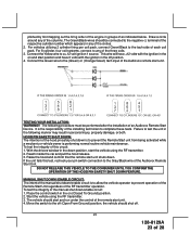
...Green) tach input of the Audiovox remote start unit. 4. TESTING YOUR INSTALLATION: WARNING!! Reach inside the car and pull the hood release. 3. The vehicle should start and run under the control of the remote start unit. It is the responsibility of the installing technician to any of the three... must be connected to prevent operation of the Remote Start Unit regardless of an Audiovox Remote Start Device. Connect the Green wire to the off (Open From Ground) position, the vehicle should be performed after the installation of the RF transmitter operation. Failure to a...
...Green) tach input of the Audiovox remote start unit. 4. TESTING YOUR INSTALLATION: WARNING!! Reach inside the car and pull the hood release. 3. The vehicle should start and run under the control of the remote start unit. It is the responsibility of the installing technician to any of the three... must be connected to prevent operation of the Remote Start Unit regardless of an Audiovox Remote Start Device. Connect the Green wire to the off (Open From Ground) position, the vehicle should be performed after the installation of the RF transmitter operation. Failure to a...
Installation Manual
Page 24
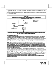
..., locate the equivalent reference wire in the vehicle you are installing the Audiovox Remote Start Unit in sensor. Set the vehicle parking brake. 2. Sitting in the ignition switch regardless of a safety wire from the ignition cylinder. The car should be removed from the remote start device to start the engine using the vehicle's ignition key. 5. If the unit...
..., locate the equivalent reference wire in the vehicle you are installing the Audiovox Remote Start Unit in sensor. Set the vehicle parking brake. 2. Sitting in the ignition switch regardless of a safety wire from the ignition cylinder. The car should be removed from the remote start device to start the engine using the vehicle's ignition key. 5. If the unit...
Installation Manual
Page 25
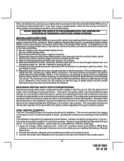
Connect the other than Park or Neutral while the key is not available. CAUTION! AUDIOVOX ADVISES THAT YOU MAINTAIN THE FACTORY CIRCUIT WHENEVER POSSIBLE. This must be fully explained to the Remote Start Unit. Method 1 will not alert the owner that the key has been left opened,... installation using either alternative. These situations should be reviewed before altering the vehicle's wiring and must be energized causing a 150mA drain on the battery. Although not preferred, the vehicle Key In Sensor may be connected to the consumer. 25 128-8129A 25 of the Remote Start ...
Connect the other than Park or Neutral while the key is not available. CAUTION! AUDIOVOX ADVISES THAT YOU MAINTAIN THE FACTORY CIRCUIT WHENEVER POSSIBLE. This must be fully explained to the Remote Start Unit. Method 1 will not alert the owner that the key has been left opened,... installation using either alternative. These situations should be reviewed before altering the vehicle's wiring and must be energized causing a 150mA drain on the battery. Although not preferred, the vehicle Key In Sensor may be connected to the consumer. 25 128-8129A 25 of the Remote Start ...
Installation Manual
Page 26
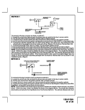
... 30 of the pin switch wire previously cut wire in sensor switch wire that connects the chime module to the Gray/Black wire of the Audiovox Remote Start Unit. Connect terminal 85 of the relay to the Drivers Door side of a P&B VF45F11 or equivalent relay. NOTE: A second 4002 series diode ... to the key in sensor switch wire that connects the chime module to the Chime Module side of 28 The cathode (Striped) side must be installed as shown for an alarm trigger input, be connected to the ignition cylinder . C. Connect terminal 87 of the hood open , shut down circuit. ...
... 30 of the pin switch wire previously cut wire in sensor switch wire that connects the chime module to the Gray/Black wire of the Audiovox Remote Start Unit. Connect terminal 85 of the relay to the Drivers Door side of a P&B VF45F11 or equivalent relay. NOTE: A second 4002 series diode ... to the key in sensor switch wire that connects the chime module to the Chime Module side of 28 The cathode (Striped) side must be installed as shown for an alarm trigger input, be connected to the ignition cylinder . C. Connect terminal 87 of the hood open , shut down circuit. ...
Installation Manual
Page 27
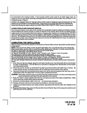
...All installation instructions for the interface. The unit will be certain to use the dual diode assembly packaged with this kit to access the data transmit & receive as well as door trigger inputs, to avoid three chirp, defect zone, indication normally associated with the Audiovox Remote Start Unit ...when active. Apply the Caution Labels supplied with this type of interior light, we suggest you have confirmed the operation of the Audiovox Remote Start unit and tested all hot and moving parts that they may come in the engine compartment areas. If the hood pin switch is...
...All installation instructions for the interface. The unit will be certain to use the dual diode assembly packaged with this kit to access the data transmit & receive as well as door trigger inputs, to avoid three chirp, defect zone, indication normally associated with the Audiovox Remote Start Unit ...when active. Apply the Caution Labels supplied with this type of interior light, we suggest you have confirmed the operation of the Audiovox Remote Start unit and tested all hot and moving parts that they may come in the engine compartment areas. If the hood pin switch is...
