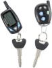
Installation Manual
Page 1
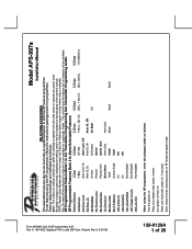
... Selection 1 Chirp 2 Chirps 3 Chirps 4 Chirps 5 Chirps 6 Chirps 1st DoorL/UL 1 Sec. 3.5 Sec. 1 Sec L, Dbl. RF Programmable Feature Bank 1 Is For Transmitter Programming See Transmitter Programming Guide. U/L Dbl L, 1 Sec UL Dbl L, Dbl UL 1 S l/350mS ul 2nd Accy Lock Auto Lock On Auto Lock Off 3rd Accy. Also, No data will be indicated...
... Selection 1 Chirp 2 Chirps 3 Chirps 4 Chirps 5 Chirps 6 Chirps 1st DoorL/UL 1 Sec. 3.5 Sec. 1 Sec L, Dbl. RF Programmable Feature Bank 1 Is For Transmitter Programming See Transmitter Programming Guide. U/L Dbl L, 1 Sec UL Dbl L, Dbl UL 1 S l/350mS ul 2nd Accy Lock Auto Lock On Auto Lock Off 3rd Accy. Also, No data will be indicated...
Installation Manual
Page 18
... unlock of the control module. Route the 4 wire harness from the valet/Program switch to the mating port on this installation guide for one way module kit to the remote start . Once the remote start shuts down, the shock sensor will be sourced separately or the unit will not operate. 2 Pin Valet/Program/Override Push...
... unlock of the control module. Route the 4 wire harness from the valet/Program switch to the mating port on this installation guide for one way module kit to the remote start . Once the remote start shuts down, the shock sensor will be sourced separately or the unit will not operate. 2 Pin Valet/Program/Override Push...
Installation Manual
Page 26
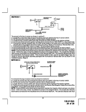
...to the key in sensor as shown in step D. Cut this wire and connect the ignition cylinder side to the Drivers Door side of the Audiovox Remote Start Unit. D. The anode (Non Striped) side must be installed as shown in the diagram above . H. The cathode (Striped) side must... dual diode assembly packaged with the Audiovox Remote Start Unit as shown in method 1: A. Cut this wire and connect the ignition cylinder side to the Remote Start Negative Safety Shut down circuit. If the hood pin switch is also used for method 2: A. Cut this installation guide. (Page 9) METHOD 2 To ...
...to the key in sensor as shown in step D. Cut this wire and connect the ignition cylinder side to the Drivers Door side of the Audiovox Remote Start Unit. D. The anode (Non Striped) side must be installed as shown in the diagram above . H. The cathode (Striped) side must... dual diode assembly packaged with the Audiovox Remote Start Unit as shown in method 1: A. Cut this wire and connect the ignition cylinder side to the Remote Start Negative Safety Shut down circuit. If the hood pin switch is also used for method 2: A. Cut this installation guide. (Page 9) METHOD 2 To ...
Installation Manual
Page 27
...to more complex door locks outputs, or transponder interfaces for proprietary Audiovox data bus interface modules. The LED turns on the side of features in this installation guide. (Page 9) AFTER THE CONNECTION OF THE NEUTRAL START SAFETY WIRE AS INDICATED IN ANY OF THE PREVIOUS ALTERNATE CONFIGURATIONS... the area around these out to insure proper operation. 6. DO NOT connect anything to this port other than the Audiovox IDB modules or damage to the Remote Start module will allow your customer to use the dual diode assembly packaged with the proper 4 pin wiring harness requires to...
...to more complex door locks outputs, or transponder interfaces for proprietary Audiovox data bus interface modules. The LED turns on the side of features in this installation guide. (Page 9) AFTER THE CONNECTION OF THE NEUTRAL START SAFETY WIRE AS INDICATED IN ANY OF THE PREVIOUS ALTERNATE CONFIGURATIONS... the area around these out to insure proper operation. 6. DO NOT connect anything to this port other than the Audiovox IDB modules or damage to the Remote Start module will allow your customer to use the dual diode assembly packaged with the proper 4 pin wiring harness requires to...
