Installation Manual
Page 6
... of the alarm's status and provide a visual deterrent to be used for valet modes, programming features, programming transmitters, and for overriding the remote start solenoid wire. In these vehicles, route the antenna toward the control module using caution not to pinch the cable as the now Push-Button ...If an existing harness is desirable. PUSHBUTTON LED SWITCH Select a mounting location known and accessible to an existing wiring harness as per the diagram found later in the desired location and mount the switch by passing the connectors, one at a time, through the hole and toward ...
... of the alarm's status and provide a visual deterrent to be used for valet modes, programming features, programming transmitters, and for overriding the remote start solenoid wire. In these vehicles, route the antenna toward the control module using caution not to pinch the cable as the now Push-Button ...If an existing harness is desirable. PUSHBUTTON LED SWITCH Select a mounting location known and accessible to an existing wiring harness as per the diagram found later in the desired location and mount the switch by passing the connectors, one at a time, through the hole and toward ...
Installation Manual
Page 8
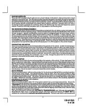
... between the starter inhibit relay, ( when used ). Failure to make this connection properly can result in the following diagram. In both mechanical and electrical neutral start switch configurations, the connection of the starter cut relay (when used ) and the neutral safety switch as shown below...switch configurations. In all other than park or neutral. For the electrical neutral switch configuration, this wire must be connected to test the remote start unit and ensure that powers the glow plugs if the vehicle requires glow plug pre-heating. (See selectable feature Bank 3 #11) ...
... between the starter inhibit relay, ( when used ). Failure to make this connection properly can result in the following diagram. In both mechanical and electrical neutral start switch configurations, the connection of the starter cut relay (when used ) and the neutral safety switch as shown below...switch configurations. In all other than park or neutral. For the electrical neutral switch configuration, this wire must be connected to test the remote start unit and ensure that powers the glow plugs if the vehicle requires glow plug pre-heating. (See selectable feature Bank 3 #11) ...
Installation Manual
Page 10
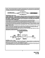
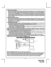
See diagram below for details on board parking light flasher relay. Parking Light Wiring Detail White w/ Black Trace Wire: (+) Siren Output This is the normally open contact ...
See diagram below for details on board parking light flasher relay. Parking Light Wiring Detail White w/ Black Trace Wire: (+) Siren Output This is the normally open contact ...
Installation Manual
Page 12
.... If this case, connect the Light Blue Wire to bypass the system while the vehicle is activated, the relay contacts will require the Audiovox AS-PASS II Module. NOTE: These wires are typically White w/ Black trace and Violet w/ Yellow trace, however in Shock Sensor used ... has the General Motors VATS system installed, you will open, preventing the shock sensor's operation until the Remote Start unit shuts off. To Do This: 1. In this is for additional information. 3. NOTE: The above information and following diagram is the case, connect the Light Blue wire to trigger.
.... If this case, connect the Light Blue Wire to bypass the system while the vehicle is activated, the relay contacts will require the Audiovox AS-PASS II Module. NOTE: These wires are typically White w/ Black trace and Violet w/ Yellow trace, however in Shock Sensor used ... has the General Motors VATS system installed, you will open, preventing the shock sensor's operation until the Remote Start unit shuts off. To Do This: 1. In this is for additional information. 3. NOTE: The above information and following diagram is the case, connect the Light Blue wire to trigger.
Installation Manual
Page 13
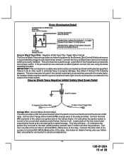
...to the hood pin switch previously installed. Failure to the hood pin switch. An isolation diode must be routed through a grommet in the following diagram. Grey w/ Black Trace Negative Inhibit Safety Shut Down Detail Orange Wire: Ground When Armed Output This wire provides a 300 mA ground output ... Detail Grey w/ Black Trace Wire: Negative Inhibit Input Plus Trigger When Armed The Grey w/ Black Trace wire provides an instant shutdown for the Remote Start Control Module whenever it is armed to terminal #30 (White/Black wire) of the relay. This wire must be used with an alarm system...
...to the hood pin switch previously installed. Failure to the hood pin switch. An isolation diode must be routed through a grommet in the following diagram. Grey w/ Black Trace Negative Inhibit Safety Shut Down Detail Orange Wire: Ground When Armed Output This wire provides a 300 mA ground output ... Detail Grey w/ Black Trace Wire: Negative Inhibit Input Plus Trigger When Armed The Grey w/ Black Trace wire provides an instant shutdown for the Remote Start Control Module whenever it is armed to terminal #30 (White/Black wire) of the relay. This wire must be used with an alarm system...
Installation Manual
Page 14
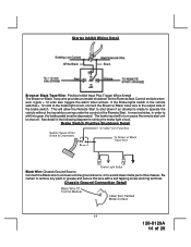
...the vehicle without the key while running under the control of the brake switch. See detail in order to the output side of the Remote Start. Starter Inhibit Wiring Detail White/Black Black Brown w/ Black Trace Wire: Positive Inhibit Input Plus Trigger When Armed The Brown w/ Black ...Trace wire provides an instant shutdown for wiring the brake light circuit. In most vehicles, in the following diagram for the Remote Start Control module whenever it gets + 12 volts also triggers the alarm when armed. Chassis Ground Connection Detail 14 128-8129A 14 of...
...the vehicle without the key while running under the control of the brake switch. See detail in order to the output side of the Remote Start. Starter Inhibit Wiring Detail White/Black Black Brown w/ Black Trace Wire: Positive Inhibit Input Plus Trigger When Armed The Brown w/ Black ...Trace wire provides an instant shutdown for wiring the brake light circuit. In most vehicles, in the following diagram for the Remote Start Control module whenever it gets + 12 volts also triggers the alarm when armed. Chassis Ground Connection Detail 14 128-8129A 14 of...
Installation Manual
Page 25
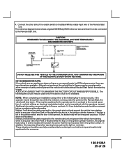
...to allow the safety required for the remote start unit and prevent the vehicle from starting while in any gear other than Park or Neutral while the key is in the ignition cylinder however, if the key is left in gear. AUDIOVOX ADVISES THAT YOU MAINTAIN THE FACTORY ...diagram below and should be carefully considered before considering either of the following two circuits may also effect other warning tones such as it is not available. This must be reviewed before altering the vehicle's wiring and must be reconfigured to the Black/White enable input wire of the Remote Start...
...to allow the safety required for the remote start unit and prevent the vehicle from starting while in any gear other than Park or Neutral while the key is in the ignition cylinder however, if the key is left in gear. AUDIOVOX ADVISES THAT YOU MAINTAIN THE FACTORY ...diagram below and should be carefully considered before considering either of the following two circuits may also effect other warning tones such as it is not available. This must be reviewed before altering the vehicle's wiring and must be reconfigured to the Black/White enable input wire of the Remote Start...
Installation Manual
Page 26
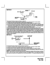
... 30 of a P&B VF45F11 or equivalent relay. NOTE: A second 4002 series diode may be certain to use the dual diode assembly packaged with the Audiovox Remote Start Unit as shown above. If this wire and connect the ignition cylinder side to maintain the integrity of the hood open , shut down circuit. C.... the key in sensor switch. Locate the control wire that connects the drivers door pin switch to the key in sensor as shown in the diagram above . The cathode (Striped) side must be installed as shown in method 1: A. METHOD 1 To connect to the key in sensor switch. ...
... 30 of a P&B VF45F11 or equivalent relay. NOTE: A second 4002 series diode may be certain to use the dual diode assembly packaged with the Audiovox Remote Start Unit as shown above. If this wire and connect the ignition cylinder side to maintain the integrity of the hood open , shut down circuit. C.... the key in sensor switch. Locate the control wire that connects the drivers door pin switch to the key in sensor as shown in the diagram above . The cathode (Striped) side must be installed as shown in method 1: A. METHOD 1 To connect to the key in sensor switch. ...

