Installation Manual
Page 4
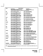
..., turn ignition Off, On, Off, On Short chirp, then 2 long chirps This Action Accesses Feature Bank 3 Remote Start Selectable Features First Press the valet switch one time Press transmitter Lock button to change or Second Press and release the... 2 chirps = tachometer input checking 1 chirp = voltage sense input checking 1 chirp = greater than 0.5 V check before start 2 chirps = less than 0.5 V check before start 2 chirps = ign 2 on during crank 3 chirps = ign 2 same as accessory 1 chirp = ign 2 off during crank 2 chirps = ign 3 on during crank 1 chirp = diagnostics off during crank...
..., turn ignition Off, On, Off, On Short chirp, then 2 long chirps This Action Accesses Feature Bank 3 Remote Start Selectable Features First Press the valet switch one time Press transmitter Lock button to change or Second Press and release the... 2 chirps = tachometer input checking 1 chirp = voltage sense input checking 1 chirp = greater than 0.5 V check before start 2 chirps = less than 0.5 V check before start 2 chirps = ign 2 on during crank 3 chirps = ign 2 same as accessory 1 chirp = ign 2 off during crank 2 chirps = ign 3 on during crank 1 chirp = diagnostics off during crank...
Installation Manual
Page 7
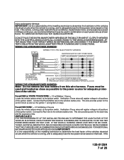
... installing technician to determine the load factor of the vehicles electrical circuits when the vehicle is running, and to the power source for the start relay and the accessory relay. IMPORTANT! If the vehicle, running , and to the vehicle's battery wire. Fused RED w/ WHITE TRACE WIRE: + 12 volt ... If the 7 128-8129A 7 of the ignition switch. IF THE VEHICLE, RUNNING UNDER LOAD WITH THE AIR CONDITIONER, HEATER BLOWER MOTOR, AND ACCESSORIES EXCEEDS 24 AMPS CONTINUOUS, WE RECOMMEND THAT TWO FUSES BE USED IN COMBINATION ON EACH POWER WIRE AS SHOWN BELOW. WIRING THE 6 PIN MAIN ...
... installing technician to determine the load factor of the vehicles electrical circuits when the vehicle is running, and to the power source for the start relay and the accessory relay. IMPORTANT! If the vehicle, running , and to the vehicle's battery wire. Fused RED w/ WHITE TRACE WIRE: + 12 volt ... If the 7 128-8129A 7 of the ignition switch. IF THE VEHICLE, RUNNING UNDER LOAD WITH THE AIR CONDITIONER, HEATER BLOWER MOTOR, AND ACCESSORIES EXCEEDS 24 AMPS CONTINUOUS, WE RECOMMEND THAT TWO FUSES BE USED IN COMBINATION ON EACH POWER WIRE AS SHOWN BELOW. WIRING THE 6 PIN MAIN ...
Installation Manual
Page 8
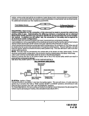
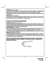
...this connection properly can result in personal injury and property damage. vehicle, running under load with the air conditioner, heater blower motor, and accessories exceed 24 Amps continuous, we recommend that powers the glow plugs if the vehicle requires glow plug pre-heating. (See selectable feature Bank ...This wire will have 0 volts when the key is the responsibility of the installing technician to test the remote start unit and ensure that the vehicle cannot start switch configurations, the connection of the Yellow wire will realize why the connection of the neutral safety switch ...
...this connection properly can result in personal injury and property damage. vehicle, running under load with the air conditioner, heater blower motor, and accessories exceed 24 Amps continuous, we recommend that powers the glow plugs if the vehicle requires glow plug pre-heating. (See selectable feature Bank ...This wire will have 0 volts when the key is the responsibility of the installing technician to test the remote start unit and ensure that the vehicle cannot start switch configurations, the connection of the Yellow wire will realize why the connection of the neutral safety switch ...
Installation Manual
Page 9
... NOTE: See programming information (Bank 3 Selection #2) concerning this wire to the "ON" or "RUN" position and is turned to allow output during the start cycle. (See feature bank 3 selection # 8) Connect this wire to the third ignition circuit in the vehicle and set up for negative switching when necessary....holders from the ignition switch. This input must be used . This wire will show + 12 volts when the ignition switch is turned to the "ACCESSORY" or "ON" and "RUN" positions, and will show 0 volts when the key is turned to ground when the vehicle's parking brake is turned...
... NOTE: See programming information (Bank 3 Selection #2) concerning this wire to the "ON" or "RUN" position and is turned to allow output during the start cycle. (See feature bank 3 selection # 8) Connect this wire to the third ignition circuit in the vehicle and set up for negative switching when necessary....holders from the ignition switch. This input must be used . This wire will show + 12 volts when the ignition switch is turned to the "ACCESSORY" or "ON" and "RUN" positions, and will show 0 volts when the key is turned to ground when the vehicle's parking brake is turned...
Installation Manual
Page 10
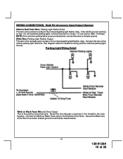
... to the vehicle parking light feed wire. Secure the Black wire of the Siren to the Red wire of the Siren. WIRING CONNECTIONS: Multi Pin Accessory Input/Output Harness White w/ Red Trace Wire: Parking Light Flasher Feed This wire is the common contact of the on wiring positive switched parking light...
... to the vehicle parking light feed wire. Secure the Black wire of the Siren to the Red wire of the Siren. WIRING CONNECTIONS: Multi Pin Accessory Input/Output Harness White w/ Red Trace Wire: Parking Light Flasher Feed This wire is the common contact of the on wiring positive switched parking light...