Z9NH-D12 Series User Manual
Page 4
... up for the first time 3-3 3.2 Powering off the computer 3-4 3.2.1 Using the OS shut down function 3-4 3.2.2 Using the dual function power switch 3-4 Chapter 4: BIOS setup 4.1 Managing and updating your BIOS 4-3 4.1.1 ASUS CrashFree BIOS 3 utility 4-3 4.1.2 ASUS EZ Flash 2 Utility 4-4 4.1.3 BUPDATER utility 4-5 4.2 BIOS setup program 4-7 4.2.1 BIOS menu screen 4-8 4.2.2 Menu bar 4-8 4.2.3 Menu items 4-9 4.2.4 Submenu items 4-9 4.2.5 Navigation keys...
... up for the first time 3-3 3.2 Powering off the computer 3-4 3.2.1 Using the OS shut down function 3-4 3.2.2 Using the dual function power switch 3-4 Chapter 4: BIOS setup 4.1 Managing and updating your BIOS 4-3 4.1.1 ASUS CrashFree BIOS 3 utility 4-3 4.1.2 ASUS EZ Flash 2 Utility 4-4 4.1.3 BUPDATER utility 4-5 4.2 BIOS setup program 4-7 4.2.1 BIOS menu screen 4-8 4.2.2 Menu bar 4-8 4.2.3 Menu items 4-9 4.2.4 Submenu items 4-9 4.2.5 Navigation keys...
Z9NH-D12 Series User Manual
Page 11
.... • Chapter 2: Hardware information This chapter lists the hardware setup procedures that you need when installing and configuring the motherboard. It includes description of the switches, jumpers, and connectors on the motherboard. • Chapter 3: Powering up This chapter describes the power up , creating, and configuring RAID sets using the available utilities...
.... • Chapter 2: Hardware information This chapter lists the hardware setup procedures that you need when installing and configuring the motherboard. It includes description of the switches, jumpers, and connectors on the motherboard. • Chapter 3: Powering up This chapter describes the power up , creating, and configuring RAID sets using the available utilities...
Z9NH-D12 Series User Manual
Page 25
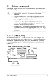
... the power cable before removing or plugging in any component, place it on them. • Whenever you uninstall any motherboard component. ASUS Z9NH-D12 Series 2-3 This is a reminder that the power supply is switched off or the power cord is detached from the wall socket before touching any component. • Use a grounded wrist strap...
... the power cable before removing or plugging in any component, place it on them. • Whenever you uninstall any motherboard component. ASUS Z9NH-D12 Series 2-3 This is a reminder that the power supply is switched off or the power cord is detached from the wall socket before touching any component. • Use a grounded wrist strap...
Z9NH-D12 Series User Manual
Page 49
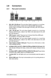
.... Activity LED indicates Infiniband activity status. 7. This 9-pin communication port is for pointing devices or other VGA-compatible devices. 6. ASUS Z9NH-D12 Series 2-27 This port allows Gigabit connection to a Local Area Network (LAN) through a network hub for the LAN port LED...Video Graphics Adapter (VGA) port. InfiniBand (QSFP). (Z9NH-D12/FDR and Z9NH-D12/10G only) This port allows connection with a QSFP cable to a Local Area Network (LAN) through a network hub. This port allows Gigabit connection to an InfiniBand switch. 8. Location LED. Refer to the table below for ...
.... Activity LED indicates Infiniband activity status. 7. This 9-pin communication port is for pointing devices or other VGA-compatible devices. 6. ASUS Z9NH-D12 Series 2-27 This port allows Gigabit connection to a Local Area Network (LAN) through a network hub for the LAN port LED...Video Graphics Adapter (VGA) port. InfiniBand (QSFP). (Z9NH-D12/FDR and Z9NH-D12/10G only) This port allows connection with a QSFP cable to a Local Area Network (LAN) through a network hub. This port allows Gigabit connection to an InfiniBand switch. 8. Location LED. Refer to the table below for ...

Z9NH-D12 Series User Manual
Page 60
... to indicate an abnormal event occurance. 3) System warning speaker (4-pin SPEAKER) This 4-pin connector is for the chassis-mounted system warning speaker. Pressing the power switch for more than four seconds while the system is ON turns the system OFF. 6) Reset button (2-pin RESET) This 2-pin connector is for system reboot...
... to indicate an abnormal event occurance. 3) System warning speaker (4-pin SPEAKER) This 4-pin connector is for the chassis-mounted system warning speaker. Pressing the power switch for more than four seconds while the system is ON turns the system OFF. 6) Reset button (2-pin RESET) This 2-pin connector is for system reboot...

Z9NH-D12 Series User Manual
Page 61
...) These leads are for chassis with intrusion sensor or microswitch. Connect the Locator LED cables to these leads to these 2-pin connector. ASUS Z9NH-D12 Series 2-39 Auxiliary panel connector (20-2 pin AUX_PANEL1) This connector is pressed. 5) Locator Button/Swich (2-pin LOCATORBTN) These leads are...front panel. The LEDs will light up when the Locator button is for additional front panel features including front panel SMB, locator LED and switch, chassis intrusion, and LAN LEDs. 1) Front panel SMB (6-1 pin FPSMB) These leads connect the front panel SMBus cable. 2) LAN ...
...) These leads are for chassis with intrusion sensor or microswitch. Connect the Locator LED cables to these leads to these 2-pin connector. ASUS Z9NH-D12 Series 2-39 Auxiliary panel connector (20-2 pin AUX_PANEL1) This connector is pressed. 5) Locator Button/Swich (2-pin LOCATORBTN) These leads are...front panel. The LEDs will light up when the Locator button is for additional front panel features including front panel SMB, locator LED and switch, chassis intrusion, and LAN LEDs. 1) Front panel SMB (6-1 pin FPSMB) These leads connect the front panel SMBus cable. 2) LAN ...

Z9NH-D12 Series User Manual
Page 65
... power cord to enter the BIOS Setup. System power 6. The system then runs the power-on the system front panel case lights up. ASUS Z9NH-D12 Series 3-3 Monitor b. Check the jumper settings and connections or call your monitor complies with a surge protector. 5. Be sure that is equipped... "power standby" feature, the monitor LED may have failed a power-on the devices in Chapter 4. Turn on test. After making all switches are running, the BIOS beeps or additional messages appear on . Connect the power to a power outlet that all the connections, replace the system...
... power cord to enter the BIOS Setup. System power 6. The system then runs the power-on the system front panel case lights up. ASUS Z9NH-D12 Series 3-3 Monitor b. Check the jumper settings and connections or call your monitor complies with a surge protector. 5. Be sure that is equipped... "power standby" feature, the monitor LED may have failed a power-on the devices in Chapter 4. Turn on test. After making all switches are running, the BIOS beeps or additional messages appear on . Connect the power to a power outlet that all the connections, replace the system...

Z9NH-D12 Series User Manual
Page 66
Click the Start button, move the cursor to shut down the computer. 3. If necessary, key in comments. 5. Click OK. 3.2.2 Using the dual function power switch While the system is checked. 4. Ensure that best describes why you are using Windows® 2008 Server: 1. 3.2 Powering off , and then click Shut Down.... 2. From the Shutdown Event Tracker, select the option that the Planned check box is ON, pressing the power switch for less than four seconds puts the system to sleep mode or to soft-off mode, depending on the right of Log off the computer...
Click the Start button, move the cursor to shut down the computer. 3. If necessary, key in comments. 5. Click OK. 3.2.2 Using the dual function power switch While the system is checked. 4. Ensure that best describes why you are using Windows® 2008 Server: 1. 3.2 Powering off , and then click Shut Down.... 2. From the Shutdown Event Tracker, select the option that the Planned check box is ON, pressing the power switch for less than four seconds puts the system to sleep mode or to soft-off mode, depending on the right of Log off the computer...
Z9NH-D12 Series User Manual
Page 70
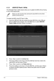
... fs0:\ fs1:\ VER: 0304 Folder Info 12/09/10 10:23p 4194304 Exit DATE: 03/13/2012 Z9NH-D12-ASUS-0304.ROM File Infor MODEL: Help Info VER: DATE: [Enter] Select or Load [Tab] Switch [Up/Down/PageUp/PageDown/Home/End] Move [Esc] Exit [F2] Backup 3. Insert the USB flash ... To update the BIOS using this utility, download the latest BIOS from the ASUS website at www.asus.com. 4.1.2 ASUS EZ Flash 2 Utility The ASUS EZ Flash 2 Utility feature allows you start using EZ Flash 2 Utility 1. Press to switch to perform the BIOS update process. Reboot the system when the update process ...
... fs0:\ fs1:\ VER: 0304 Folder Info 12/09/10 10:23p 4194304 Exit DATE: 03/13/2012 Z9NH-D12-ASUS-0304.ROM File Infor MODEL: Help Info VER: DATE: [Enter] Select or Load [Tab] Switch [Up/Down/PageUp/PageDown/Home/End] Move [Esc] Exit [F2] Backup 3. Insert the USB flash ... To update the BIOS using this utility, download the latest BIOS from the ASUS website at www.asus.com. 4.1.2 ASUS EZ Flash 2 Utility The ASUS EZ Flash 2 Utility feature allows you start using EZ Flash 2 Utility 1. Press to switch to perform the BIOS update process. Reboot the system when the update process ...

Z9NH-D12 Series User Manual
Page 74
... →←: Select Screen ↑↓: Select Item Enter: Select Item +/-: Change Opt. PI 0.9 0303 x64 08/22/2012 Set the Date, Use Tab to switch between Data elements. Copyright (C) 2011 American Megatrends, Inc. Navigation keys 4.2.2 Menu bar The menu bar on top of the screen has the following main items...
... →←: Select Screen ↑↓: Select Item Enter: Select Item +/-: Change Opt. PI 0.9 0303 x64 08/22/2012 Set the Date, Use Tab to switch between Data elements. Copyright (C) 2011 American Megatrends, Inc. Navigation keys 4.2.2 Menu bar The menu bar on top of the screen has the following main items...

Z9NH-D12 Series User Manual
Page 76
... (C) 2011 American Megatrends, Inc. 4.3.1 System Date [Day xx/xx/xxxx] Allows you to set the system date. 4.3.2 System Time [xx:xx:xx] Allows you to switch between Data elements. Aptio Setup Utility - System Date System Time [Sat 01/15/2005] [15:07:28] Access Level Memory Information Total Memory Processor CPU...
... (C) 2011 American Megatrends, Inc. 4.3.1 System Date [Day xx/xx/xxxx] Allows you to set the system date. 4.3.2 System Time [xx:xx:xx] Allows you to switch between Data elements. Aptio Setup Utility - System Date System Time [Sat 01/15/2005] [15:07:28] Access Level Memory Information Total Memory Processor CPU...

Z9NH-D12 Series User Manual
Page 161
5. Type the following commands when using a Legacy floppy. Yes No 6. When the installation is completed, DO NOT click Reboot. When asked if you wish to load any more driver disks? Follow the onscreen instructions to the command-line interface from graphic user interface. 8. Do you will load additional RAID controller drivers, select No, then press . Press + + to switch to finish the OS installation. 7. More Driver Disks? mkdir /mnt/driver mount /dev/fd0 /mnt/driver cd /mnt/driver sh replace_ahci.sh reboot ASUS Z9NH-D12 Series 6-9
5. Type the following commands when using a Legacy floppy. Yes No 6. When the installation is completed, DO NOT click Reboot. When asked if you wish to load any more driver disks? Follow the onscreen instructions to the command-line interface from graphic user interface. 8. Do you will load additional RAID controller drivers, select No, then press . Press + + to switch to finish the OS installation. 7. More Driver Disks? mkdir /mnt/driver mount /dev/fd0 /mnt/driver cd /mnt/driver sh replace_ahci.sh reboot ASUS Z9NH-D12 Series 6-9