
User Guide
Page 1
Motherboard Z97-E/USB 3.1
Motherboard Z97-E/USB 3.1

User Guide
Page 3
Contents Safety information iv About this guide iv Package contents vi Z97-E/USB 3.1 specifications summary vi Chapter 1: Product introduction 1.1 Before you proceed 1-1 1.2 Motherboard overview 1-2 1.3 Central Processing Unit (CPU 1-4 1.4 System memory 1-8 1.5 Expansion slots 1-11 1.6 Headers 1-13 1.7 Connectors 1-14 1.8 Onboard ... 2.4 Main menu 2-17 2.5 Ai Tweaker menu 2-19 2.6 Advanced menu 2-30 2.7 Monitor menu 2-40 2.8 Boot menu 2-44 2.9 Tool menu 2-50 2.10 Exit menu 2-51 Appendices Notices...A-1 ASUS contact information A-4 iii
Contents Safety information iv About this guide iv Package contents vi Z97-E/USB 3.1 specifications summary vi Chapter 1: Product introduction 1.1 Before you proceed 1-1 1.2 Motherboard overview 1-2 1.3 Central Processing Unit (CPU 1-4 1.4 System memory 1-8 1.5 Expansion slots 1-11 1.6 Headers 1-13 1.7 Connectors 1-14 1.8 Onboard ... 2.4 Main menu 2-17 2.5 Ai Tweaker menu 2-19 2.6 Advanced menu 2-30 2.7 Monitor menu 2-40 2.8 Boot menu 2-44 2.9 Tool menu 2-50 2.10 Exit menu 2-51 Appendices Notices...A-1 ASUS contact information A-4 iii

User Guide
Page 6
... AMD® Quad-GPU CrossFireX™ Technology (continued on the CPU types. Intel® HD Graphics support Multi-VGA output support: HDMI, DVI, RGB port - Z97-E/USB 3.1 2 x Serial ATA 6.0 Gb/s cables 1 x I/O Shield Support DVD User Guide If any of individual CPUs. Supports HDMI with max. Supports RGB with max. resolution 1920 x...) vi resolution 1920 x 1200@60Hz Supports Intel® InTru™ 3D/Quick Sync Video/Clear Video HD Technology/ Insider™ Supports up to www.asus.com for the following items. Motherboard Cables Accessories Application DVD Documentation...
... AMD® Quad-GPU CrossFireX™ Technology (continued on the CPU types. Intel® HD Graphics support Multi-VGA output support: HDMI, DVI, RGB port - Z97-E/USB 3.1 2 x Serial ATA 6.0 Gb/s cables 1 x I/O Shield Support DVD User Guide If any of individual CPUs. Supports HDMI with max. Supports RGB with max. resolution 1920 x...) vi resolution 1920 x 1200@60Hz Supports Intel® InTru™ 3D/Quick Sync Video/Clear Video HD Technology/ Insider™ Supports up to www.asus.com for the following items. Motherboard Cables Accessories Application DVD Documentation...

User Guide
Page 7
...-detection, multi-streaming, and front panel jack-retasking Intel® Z97 Express Chipset - supports ASUS USB 3.1 Boost - 2 x USB 3.1/3.0/2.0 ports at back panel) ASMedia® USB3.1 controller - ASUS ESD Guards - Audio amplifier: Provides the highest-quality sound for left... ports) - 1 x M.2 Socket 3* - 4 x SATA 6.0 Gb/s ports (gray) - Short circuit damage prevention - Z97-E/USB 3.1 specifications summary Storage LAN Audio USB ASUS Exclusive Features Intel® Z97 Express Chipset with RAID 0, 1, 5, 10 and Intel® Rapid Storage Technology 13 support - 1 x SATA Express port (gray...
...-detection, multi-streaming, and front panel jack-retasking Intel® Z97 Express Chipset - supports ASUS USB 3.1 Boost - 2 x USB 3.1/3.0/2.0 ports at back panel) ASMedia® USB3.1 controller - ASUS ESD Guards - Audio amplifier: Provides the highest-quality sound for left... ports) - 1 x M.2 Socket 3* - 4 x SATA 6.0 Gb/s ports (gray) - Short circuit damage prevention - Z97-E/USB 3.1 specifications summary Storage LAN Audio USB ASUS Exclusive Features Intel® Z97 Express Chipset with RAID 0, 1, 5, 10 and Intel® Rapid Storage Technology 13 support - 1 x SATA Express port (gray...

User Guide
Page 8
... Fanless Design: PCH Heat-sink & MOS Heatsink solution Precision Tweaker 2 - ASUS Q-Slot Quiet Thermal Design - EPU Interactive HomeCloud Media Streamer - vPCH: 154-step Chipset voltage control SFS (Stepless Frequency Selection) - Z97-E/USB 3.1 specifications summary ASUS Exclusive Features ASUS Quiet Thermal Solution ASUS Exclusive Overclocking Features ASUS EPU - ASUS O.C. BCLK/PCIE frequency tuning from your PC status with smart...
... Fanless Design: PCH Heat-sink & MOS Heatsink solution Precision Tweaker 2 - ASUS Q-Slot Quiet Thermal Design - EPU Interactive HomeCloud Media Streamer - vPCH: 154-step Chipset voltage control SFS (Stepless Frequency Selection) - Z97-E/USB 3.1 specifications summary ASUS Exclusive Features ASUS Quiet Thermal Solution ASUS Exclusive Overclocking Features ASUS EPU - ASUS O.C. BCLK/PCIE frequency tuning from your PC status with smart...

User Guide
Page 9
...Z97-E/USB 3.1 specifications summary Rear Panel I/O ports Internal I/O Connectors BIOS 1 x PS/2 keyboard/mouse port 1 x HDMI port 1 x DVI port 1 x VGA port 1 x Intel LAN (RJ45) port 2 x USB 3.1/3.0/2.0 ports (teal blue) 2 x USB 3.0/2.0 ports (blue) 2 x USB 2.0/1.1 ports 7.1-channel Audio I/O ports(6-jacks) 1 x USB 3.0/2.0 connectors support additional 2 USB ports (19-pin) 3 x USB 2.0/1/1 connectors support additional 6 USB...AMI BIOS, PnP, DMI2.7, WfM2.0, SM BIOS 2.8, ACPI 5.0, Multi-language BIOS, ASUS EZ Flash 2, CrashFree BIOS 3, F6 Qfan Control, F11 EZ Tuning Wizard, F3 My Favorites & ...
...Z97-E/USB 3.1 specifications summary Rear Panel I/O ports Internal I/O Connectors BIOS 1 x PS/2 keyboard/mouse port 1 x HDMI port 1 x DVI port 1 x VGA port 1 x Intel LAN (RJ45) port 2 x USB 3.1/3.0/2.0 ports (teal blue) 2 x USB 3.0/2.0 ports (blue) 2 x USB 2.0/1.1 ports 7.1-channel Audio I/O ports(6-jacks) 1 x USB 3.0/2.0 connectors support additional 2 USB ports (19-pin) 3 x USB 2.0/1/1 connectors support additional 6 USB...AMI BIOS, PnP, DMI2.7, WfM2.0, SM BIOS 2.8, ACPI 5.0, Multi-language BIOS, ASUS EZ Flash 2, CrashFree BIOS 3, F6 Qfan Control, F11 EZ Tuning Wizard, F3 My Favorites & ...
User Guide
Page 11
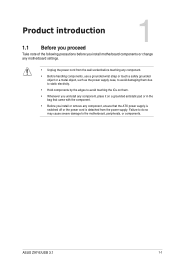
... wall socket before touching any component, ensure that the ATX power supply is switched off or the power cord is detached from the power supply. ASUS Z97-E/USB 3.1 1-1
... wall socket before touching any component, ensure that the ATX power supply is switched off or the power cord is detached from the power supply. ASUS Z97-E/USB 3.1 1-1

User Guide
Page 12
Unplug the power cord before installing or removing the motherboard. Doing so can cause you install the motherboard, study the configuration of the chassis Z97-E/USB 3.1 1-2 Chapter 1: Product introduction Place this side towards the rear of your chassis to the chassis. Do not overtighten the screws! The edge with external ports ...
Unplug the power cord before installing or removing the motherboard. Doing so can cause you install the motherboard, study the configuration of the chassis Z97-E/USB 3.1 1-2 Chapter 1: Product introduction Place this side towards the rear of your chassis to the chassis. Do not overtighten the screws! The edge with external ports ...

User Guide
Page 14
... Intel® Core™ i7 / Core™ i5 / Core™ i3, Pentium® , and Celeron® processors. USB 2.0 connectors (10-1 pin USB910, USB1112, USB1314) 13. Z97-E/USB 3.1 Z97-E/USB 3.1 CPU socket LGA1150 1-4 Chapter 1: Product introduction DDR3 DIMM slots 6. USB 3.0 connector (20-1 pin USB3_12) 7. Clear RTC RAM (2-pin CLRTC) 10. Intel® LGA1150 CPU socket 4. Intel®...
... Intel® Core™ i7 / Core™ i5 / Core™ i3, Pentium® , and Celeron® processors. USB 2.0 connectors (10-1 pin USB910, USB1112, USB1314) 13. Z97-E/USB 3.1 Z97-E/USB 3.1 CPU socket LGA1150 1-4 Chapter 1: Product introduction DDR3 DIMM slots 6. USB 3.0 connector (20-1 pin USB3_12) 7. Clear RTC RAM (2-pin CLRTC) 10. Intel® LGA1150 CPU socket 4. Intel®...

User Guide
Page 15
... before installing the CPU. • Ensure that the PnP cap is missing, or if you install the correct CPU designed for the LGA1150 socket only. ASUS will process Return Merchandise Authorization (RMA) requests only if the motherboard comes with the cap on the socket and the socket contacts are not bent... see any damage to the socket contacts resulting from incorrect CPU installation/removal, or misplacement/loss/incorrect removal of the PnP cap. 1.3.1 Installing the CPU 1 A B 2 3 ASUS Z97-E/USB 3.1 1-5
... before installing the CPU. • Ensure that the PnP cap is missing, or if you install the correct CPU designed for the LGA1150 socket only. ASUS will process Return Merchandise Authorization (RMA) requests only if the motherboard comes with the cap on the socket and the socket contacts are not bent... see any damage to the socket contacts resulting from incorrect CPU installation/removal, or misplacement/loss/incorrect removal of the PnP cap. 1.3.1 Installing the CPU 1 A B 2 3 ASUS Z97-E/USB 3.1 1-5
User Guide
Page 17
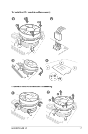
To install the CPU heatsink and fan assembly 1 A B 2 B A 3 4 To uninstall the CPU heatsink and fan assembly 1 2 A B B A ASUS Z97-E/USB 3.1 1-7
To install the CPU heatsink and fan assembly 1 A B 2 B A 3 4 To uninstall the CPU heatsink and fan assembly 1 2 A B B A ASUS Z97-E/USB 3.1 1-7

User Guide
Page 18
Recommended memory configurations 1-8 Chapter 1: Product introduction According to Intel® CPU spec, DIMM voltage below . Z97-E/USB 3.1 Z97-E/USB 3.1 240-pin DDR3 DIMM sockets 1.4.2 Memory configurations You may install 2 GB, 4 GB, and 8 GB unbuffered non-ECC DDR3 DIMMs into the DIMM sockets. DO NOT ...
Recommended memory configurations 1-8 Chapter 1: Product introduction According to Intel® CPU spec, DIMM voltage below . Z97-E/USB 3.1 Z97-E/USB 3.1 240-pin DDR3 DIMM sockets 1.4.2 Memory configurations You may install 2 GB, 4 GB, and 8 GB unbuffered non-ECC DDR3 DIMMs into the DIMM sockets. DO NOT ...

User Guide
Page 19
... usable memory for overclocking may install varying memory sizes in the BIOS for the hyper DIMM support. • Visit the ASUS website for the dual-channel configuration. For effective use a more efficient memory cooling system to support a full memory load (4 DIMMs). •...• Memory modules with the same CAS latency. or D.O.C.P. The system maps the total size of the lower-sized channel for the latest QVL. ASUS Z97-E/USB 3.1 1-9 Any excess memory from the higher-sized channel is the standard way of accessing information from the same vendor. Load the X.M.P. •...
... usable memory for overclocking may install varying memory sizes in the BIOS for the hyper DIMM support. • Visit the ASUS website for the dual-channel configuration. For effective use a more efficient memory cooling system to support a full memory load (4 DIMMs). •...• Memory modules with the same CAS latency. or D.O.C.P. The system maps the total size of the lower-sized channel for the latest QVL. ASUS Z97-E/USB 3.1 1-9 Any excess memory from the higher-sized channel is the standard way of accessing information from the same vendor. Load the X.M.P. •...

User Guide
Page 21
... cord before adding or removing expansion cards. Failure to do not need to install expansion cards. See Chapter 2 for the card. 2. ASUS Z97-E/USB 3.1 1-11 Align the card connector with the screw you physical injury and damage motherboard components. 1.5.1 Installing an expansion card To install an..., making the system unstable and the card inoperable. 1.5.3 PCI slots The PCI slot supports cards such as a LAN card, SCSI card, USB card, and other cards that comply with PCI specifications. 1.5.4 PCI Express 2.0 x1 slots This motherboard supports PCI Express x1 network cards, SCSI...
... cord before adding or removing expansion cards. Failure to do not need to install expansion cards. See Chapter 2 for the card. 2. ASUS Z97-E/USB 3.1 1-11 Align the card connector with the screw you physical injury and damage motherboard components. 1.5.1 Installing an expansion card To install an..., making the system unstable and the card inoperable. 1.5.3 PCI slots The PCI slot supports cards such as a LAN card, SCSI card, USB card, and other cards that comply with PCI specifications. 1.5.4 PCI Express 2.0 x1 slots This motherboard supports PCI Express x1 network cards, SCSI...
User Guide
Page 23
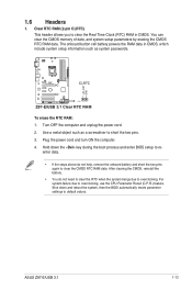
.... You can clear the CMOS memory of date, and system setup parameters by erasing the CMOS RTC RAM data. Z97-E/USB 3.1 CLRTC +3V_BAT GND PIN 1 Z97-E/USB 3.1 Clear RTC RAM To erase the RTC RAM: 1. ASUS Z97-E/USB 3.1 1-13 1.6 Headers 1. Turn OFF the computer and unplug the power cord. 2. Use a metal object such as system passwords. Plug...
.... You can clear the CMOS memory of date, and system setup parameters by erasing the CMOS RTC RAM data. Z97-E/USB 3.1 CLRTC +3V_BAT GND PIN 1 Z97-E/USB 3.1 Clear RTC RAM To erase the RTC RAM: 1. ASUS Z97-E/USB 3.1 1-13 1.6 Headers 1. Turn OFF the computer and unplug the power cord. 2. Use a metal object such as system passwords. Plug...

User Guide
Page 25
... displays under BIOS, and one display under DOS. • Intel display architecture design supports the following table for USB 2.0/1.1 devices. This port is not compatible with DVI-I. 9. ASUS Z97-E/USB 3.1 1-15 HDMI port. 4. 7.1-channel audio ports. These 9-pin Universal Serial Bus (USB) ports are controlled by the xHCI controller. These two 4-pin Universal Serial Bus...
... displays under BIOS, and one display under DOS. • Intel display architecture design supports the following table for USB 2.0/1.1 devices. This port is not compatible with DVI-I. 9. ASUS Z97-E/USB 3.1 1-15 HDMI port. 4. 7.1-channel audio ports. These 9-pin Universal Serial Bus (USB) ports are controlled by the xHCI controller. These two 4-pin Universal Serial Bus...

User Guide
Page 26
... and data. A TPM system also helps enhance the network security, protects digital identities, and ensures platform integrity. COM PIN 1 Z97-E/USB 3.1 Z97-E/USB 3.1 Serial port (COM) connector The COM module is for a serial (COM) port. LPCPD# GND +3VSB NC LAD0 +3V LAD3 PCIRST# LFRAME# ...LCLK Z97-E/USB 3.1 TPM PIN 1 NC CLKRUN# SERIRQ NC GND LAD1 LAD2 NC GND Z97-E/USB 3.1 TPM connector 1-16 Chapter 1: Product introduction RXD DTR DSR CTS DCD TXD GND RTS RI 1.7.2 Internal connectors ...
... and data. A TPM system also helps enhance the network security, protects digital identities, and ensures platform integrity. COM PIN 1 Z97-E/USB 3.1 Z97-E/USB 3.1 Serial port (COM) connector The COM module is for a serial (COM) port. LPCPD# GND +3VSB NC LAD0 +3V LAD3 PCIRST# LFRAME# ...LCLK Z97-E/USB 3.1 TPM PIN 1 NC CLKRUN# SERIRQ NC GND LAD1 LAD2 NC GND Z97-E/USB 3.1 TPM connector 1-16 Chapter 1: Product introduction RXD DTR DSR CTS DCD TXD GND RTS RI 1.7.2 Internal connectors ...
User Guide
Page 27
...CPU fan of maximum 1 A (12 W) fan power. • The CPU_FAN connector and CHA_FAN connectors support the ASUS FAN Xpert 3 feature. • The CPU fan connector detects the type of the connector. To set these ... Fan 1/2/3 Q-Fan Control items in BIOS. • The chassis fan connectors support DC and PWM modes. ASUS Z97-E/USB 3.1 1-17 A B CPU_FAN CHA_FAN2 A B C CPU FAN PWM CPU FAN IN CPU FAN PWR GND CHA FAN PWM... IN CHA FAN PWR GND Z97-E/USB 3.1 D C D CHA_FAN1 CHA_FAN3 GND CHA FAN PWR CHA FAN IN CHA FAN PWM CHA FAN PWM CHA FAN IN CHA FAN PWR GND Z97-E/USB 3.1 Fan connectors Do not...
...CPU fan of maximum 1 A (12 W) fan power. • The CPU_FAN connector and CHA_FAN connectors support the ASUS FAN Xpert 3 feature. • The CPU fan connector detects the type of the connector. To set these ... Fan 1/2/3 Q-Fan Control items in BIOS. • The chassis fan connectors support DC and PWM modes. ASUS Z97-E/USB 3.1 1-17 A B CPU_FAN CHA_FAN2 A B C CPU FAN PWM CPU FAN IN CPU FAN PWR GND CHA FAN PWM... IN CHA FAN PWR GND Z97-E/USB 3.1 D C D CHA_FAN1 CHA_FAN3 GND CHA FAN PWR CHA FAN IN CHA FAN PWM CHA FAN PWM CHA FAN IN CHA FAN PWR GND Z97-E/USB 3.1 Fan connectors Do not...

User Guide
Page 28
...1 +5 Volts GND +5 Volts GND +3 Volts +3 Volts PIN 1 GND +5 Volts +5 Volts +5 Volts -5 Volts GND GND GND PSON# GND -12 Volts +3 Volts Z97-E/USB 3.1 ATX power connectors • For a fully configured system, we recommend that complies with ATX 12 V Specification 2.0 (or later version) and provides a minimum power of ...power output when configuring a system with 1000W power or above to the Recommended Power Supply Wattage Calculator at http://support.asus. 4. ATX power connectors (24-pin EATXPWR, 8-pin EATX12V) These connectors are designed to install additional devices.
...1 +5 Volts GND +5 Volts GND +3 Volts +3 Volts PIN 1 GND +5 Volts +5 Volts +5 Volts -5 Volts GND GND GND PSON# GND -12 Volts +3 Volts Z97-E/USB 3.1 ATX power connectors • For a fully configured system, we recommend that complies with ATX 12 V Specification 2.0 (or later version) and provides a minimum power of ...power output when configuring a system with 1000W power or above to the Recommended Power Supply Wattage Calculator at http://support.asus. 4. ATX power connectors (24-pin EATXPWR, 8-pin EATX12V) These connectors are designed to install additional devices.
User Guide
Page 29
ASUS Z97-E/USB 3.1 1-19 Connect one end of the motherboard's high-definition audio capability. •..., set the Front Panel Type item in the BIOS setup to [HD]. AGND NC SENSE1_RETUR SENSE2_RETUR AGND NC NC NC Z97-E/USB 3.1 AAFP PIN 1 PIN 1 MIC2 MICPWR Line out_R NC Line out_L PORT1 L PORT1 R PORT2 R SENSE_SEND PORT2 L... HD-audio-compliant Legacy AC'97 pin definition compliant definition Z97-E/USB 3.1 Front panel audio connector • We recommend that supports either HD Audio or legacy AC`97 audio standard. By ...
ASUS Z97-E/USB 3.1 1-19 Connect one end of the motherboard's high-definition audio capability. •..., set the Front Panel Type item in the BIOS setup to [HD]. AGND NC SENSE1_RETUR SENSE2_RETUR AGND NC NC NC Z97-E/USB 3.1 AAFP PIN 1 PIN 1 MIC2 MICPWR Line out_R NC Line out_L PORT1 L PORT1 R PORT2 R SENSE_SEND PORT2 L... HD-audio-compliant Legacy AC'97 pin definition compliant definition Z97-E/USB 3.1 Front panel audio connector • We recommend that supports either HD Audio or legacy AC`97 audio standard. By ...

