User Guide
Page 14
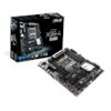
Package contents Check your motherboard package for the following items ASUS X99-A/USB 3.1 motherboard 4 x Serial ATA 6 Gb/s cables 1 x ASUS Q-Shield 1 x ASUS SLI™ bridge connector 1 x 2-in-1 ASUS Q-Connector kit User Manual Support DVD Technical documentations • If any of the above items is damaged or missing, contact your retailer. • The illustrated items above are for reference only. Actual product specifications may vary with different models. xiv
Package contents Check your motherboard package for the following items ASUS X99-A/USB 3.1 motherboard 4 x Serial ATA 6 Gb/s cables 1 x ASUS Q-Shield 1 x ASUS SLI™ bridge connector 1 x 2-in-1 ASUS Q-Connector kit User Manual Support DVD Technical documentations • If any of the above items is damaged or missing, contact your retailer. • The illustrated items above are for reference only. Actual product specifications may vary with different models. xiv
User Guide
Page 17
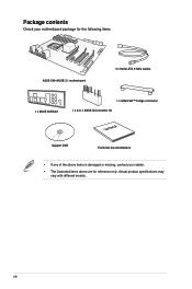
It utilizes the serial point-to-point links, which shares bandwidth with the speed of up to 32 Gb/s. Chapter 1 ASUS X99-A/USB 3.1 1-1 Chapter 1: Product Introduction Product introduction 1.1 Special features 1 1.1.1 Product highlights LGA2011-v3 socket for Intel® Core™... i7 processors. SATA Express support SATA Express provides faster data transfer speeds of the SSDs. Intel® X99 Express Chipset Intel® X99 Express Chipset is dedicated only to PCIe 1.0/2.0 devices. 3-WAY SLI and Quad GPU CrossFireX™ Support This motherboad supports...
It utilizes the serial point-to-point links, which shares bandwidth with the speed of up to 32 Gb/s. Chapter 1 ASUS X99-A/USB 3.1 1-1 Chapter 1: Product Introduction Product introduction 1.1 Special features 1 1.1.1 Product highlights LGA2011-v3 socket for Intel® Core™... i7 processors. SATA Express support SATA Express provides faster data transfer speeds of the SSDs. Intel® X99 Express Chipset Intel® X99 Express Chipset is dedicated only to PCIe 1.0/2.0 devices. 3-WAY SLI and Quad GPU CrossFireX™ Support This motherboad supports...
User Guide
Page 19
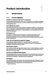
... install or remove any component, ensure that the ATX power supply is switched off or the power cord is detached from the power supply. Chapter 1 ASUS X99-A/USB 3.1 1-3 1.2 Motherboard overview 1.2.1 Before you proceed Take note of the following precautions before you install motherboard components or change any motherboard settings. • Unplug the power...
... install or remove any component, ensure that the ATX power supply is switched off or the power cord is detached from the power supply. Chapter 1 ASUS X99-A/USB 3.1 1-3 1.2 Motherboard overview 1.2.1 Before you proceed Take note of the following precautions before you install motherboard components or change any motherboard settings. • Unplug the power...
User Guide
Page 21
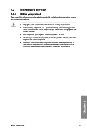
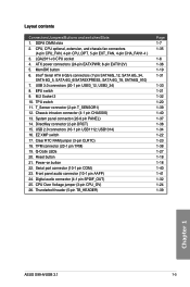
...Serial ATA 6 Gb/s connectors (7-pin SATA6G_12, SATA 6G_34, SATA 6G_5, SATA 6G_6/SATAEXPRESS, SATA 6G_78, SATA6G_910) 7. DirectKey connector (2-pin DRCT) 15. USB 2.0 connectors (10-1 pin USB1112; TPM connector (20-1 pin TPM) 19. CPU Over Voltage jumper (3-pin CPU_OV) 26. LGA2011-v3 CPU socket 4....1-32 1-20 1-39 1-40 1-37 1-38 1-34 1-22 1-23 1-38 1-27 1-18 1-18 1-40 1-41 1-32 1-24 1-39 Chapter 1 ASUS X99-A/USB 3.1 1-5 CPU, CPU optional, extension, and chassis fan connectors (4-pin CPU_FAN, 4-pin CPU_OPT, 5-pin EXT_FAN, 4-pin CHA_FAN1-4 ) 3. Digital audio connector (4-1 pin SPDIF_OUT) ...
...Serial ATA 6 Gb/s connectors (7-pin SATA6G_12, SATA 6G_34, SATA 6G_5, SATA 6G_6/SATAEXPRESS, SATA 6G_78, SATA6G_910) 7. DirectKey connector (2-pin DRCT) 15. USB 2.0 connectors (10-1 pin USB1112; TPM connector (20-1 pin TPM) 19. CPU Over Voltage jumper (3-pin CPU_OV) 26. LGA2011-v3 CPU socket 4....1-32 1-20 1-39 1-40 1-37 1-38 1-34 1-22 1-23 1-38 1-27 1-18 1-18 1-40 1-41 1-32 1-24 1-39 Chapter 1 ASUS X99-A/USB 3.1 1-5 CPU, CPU optional, extension, and chassis fan connectors (4-pin CPU_FAN, 4-pin CPU_OPT, 5-pin EXT_FAN, 4-pin CHA_FAN1-4 ) 3. Digital audio connector (4-1 pin SPDIF_OUT) ...
User Guide
Page 23
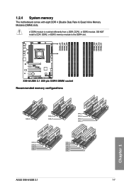
A DDR4 module is notched differently from a DDR, DDR2, or DDR3 module. DO NOT install a DDR, DDR2, or DDR3 memory module to the DDR4 slot. 1.2.4 System memory The motherboard comes with eight DDR 4 (Double Data Rate 4) Quad Inline Memory Modules (DIMM) slots. Recommended memory configurations Chapter 1 ASUS X99-A/USB 3.1 1-7
A DDR4 module is notched differently from a DDR, DDR2, or DDR3 module. DO NOT install a DDR, DDR2, or DDR3 memory module to the DDR4 slot. 1.2.4 System memory The motherboard comes with eight DDR 4 (Double Data Rate 4) Quad Inline Memory Modules (DIMM) slots. Recommended memory configurations Chapter 1 ASUS X99-A/USB 3.1 1-7
User Guide
Page 31
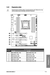
Chapter 1 Slot No. 1 2 3 4 5 6 40-LANE PCIe 3.0/2.0 x16_1 slot PCIe 2.0 x1_1 slot PCIe 2.0 x16_2 slot PCIe 3.0/2.0 x16_3 slot PCIe 2.0 x1_2 slot PCIe 3.0/2.0 x16_4 slot Slot Description 28-LANE PCIe 3.0/2.0 x16_1 slot PCIe 2.0 x1_1 slot PCIe 2.0 x16_2 slot PCIe 3.0/2.0 x16_3 slot PCIe 2.0 x1_2 slot PCIe 3.0/2.0 x16_4 slot ASUS X99-A/USB 3.1 1-15 Failure to do so may cause you physical injury and damage motherboard components. 1.2.5 Expansion slots Unplug the power cord before adding or removing expansion cards.
Chapter 1 Slot No. 1 2 3 4 5 6 40-LANE PCIe 3.0/2.0 x16_1 slot PCIe 2.0 x1_1 slot PCIe 2.0 x16_2 slot PCIe 3.0/2.0 x16_3 slot PCIe 2.0 x1_2 slot PCIe 3.0/2.0 x16_4 slot Slot Description 28-LANE PCIe 3.0/2.0 x16_1 slot PCIe 2.0 x1_1 slot PCIe 2.0 x16_2 slot PCIe 3.0/2.0 x16_3 slot PCIe 2.0 x1_2 slot PCIe 3.0/2.0 x16_4 slot ASUS X99-A/USB 3.1 1-15 Failure to do so may cause you physical injury and damage motherboard components. 1.2.5 Expansion slots Unplug the power cord before adding or removing expansion cards.
User Guide
Page 33
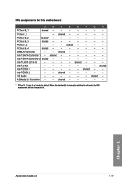
... 2 shared - - - - - - - shared - - - - - shared - - - - - * PCIe x16_2 is manually switched to x4 mode, the IRQ assignment will be changed to x1 mode by default. shared - - - - - shared - - Chapter 1 ASUS X99-A/USB 3.1 1-17 PCIe x1_1 - shared - - - - shared Intel® EHCI 1 - - - - - HD Audio - - - - - - shared - Intel® EHCI 2 - - IRQ assignments for this motherboard A B C D E F G H PCIe x16_1 shared - - - - - - - ASMedia U3 Controller...
... 2 shared - - - - - - - shared - - - - - shared - - - - - * PCIe x16_2 is manually switched to x4 mode, the IRQ assignment will be changed to x1 mode by default. shared - - - - - shared - - Chapter 1 ASUS X99-A/USB 3.1 1-17 PCIe x1_1 - shared - - - - shared Intel® EHCI 1 - - - - - HD Audio - - - - - - shared - Intel® EHCI 2 - - IRQ assignments for this motherboard A B C D E F G H PCIe x16_1 shared - - - - - - - ASMedia U3 Controller...
User Guide
Page 35
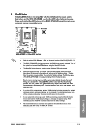
.... • The MemOK! button to BIOS overclocking, press the MemOK! ASUS X99-A/USB 3.1 1-19 Chapter 1 To stop memory tuning, turn off the computer and...not compatible with ones recommended in the Memory QVL (Qualified Vendors Lists) in this user manual or at www.asus.com. • If you download and update to test one set of the DIAG_DRAM LED. • The.... • Refer to section 1.2.8 Onboard LEDs for the system to the latest BIOS version from www.asus.com after the whole tuning process, the DIAG_DRAM LED lights continuously. button Installing DIMMs that you turn off...
.... • The MemOK! button to BIOS overclocking, press the MemOK! ASUS X99-A/USB 3.1 1-19 Chapter 1 To stop memory tuning, turn off the computer and...not compatible with ones recommended in the Memory QVL (Qualified Vendors Lists) in this user manual or at www.asus.com. • If you download and update to test one set of the DIAG_DRAM LED. • The.... • Refer to section 1.2.8 Onboard LEDs for the system to the latest BIOS version from www.asus.com after the whole tuning process, the DIAG_DRAM LED lights continuously. button Installing DIMMs that you turn off...

User Guide
Page 37
... will use the last setting you enable the EPU switch. 5. Refer to automatically detect the current PC loadings and intelligently moderate the power consumption. Chapter 1 ASUS X99-A/USB 3.1 1-21
... will use the last setting you enable the EPU switch. 5. Refer to automatically detect the current PC loadings and intelligently moderate the power consumption. Chapter 1 ASUS X99-A/USB 3.1 1-21

User Guide
Page 39
... reboot the system so the BIOS can clear the CMOS memory of date, time, and system setup parameters by erasing the CMOS RTC RAM data. ASUS X99-A/USB 3.1 1-23 Chapter 1 You must turn ON the computer. 4. You can automatically reset parameter settings to default values. • Due to pins 1-2. 3. 1.2.7 Jumpers 1. After the CMOS...
... reboot the system so the BIOS can clear the CMOS memory of date, time, and system setup parameters by erasing the CMOS RTC RAM data. ASUS X99-A/USB 3.1 1-23 Chapter 1 You must turn ON the computer. 4. You can automatically reset parameter settings to default values. • Due to pins 1-2. 3. 1.2.7 Jumpers 1. After the CMOS...

User Guide
Page 41
If an error is found, the critical component's LED stays lit up when the TPU switch is solved. 2. POST State LEDs The POST State LEDs provide the status of these key components during POST (Power-On-Self Test): CPU, memory modules, VGA card, and hard disk drives. Chapter 1 ASUS X99-A/USB 3.1 1-25 1.2.8 Onboard LEDs 1. TPU LED (TPU_LED) The TPU LED lights up until the problem is enabled.
If an error is found, the critical component's LED stays lit up when the TPU switch is solved. 2. POST State LEDs The POST State LEDs provide the status of these key components during POST (Power-On-Self Test): CPU, memory modules, VGA card, and hard disk drives. Chapter 1 ASUS X99-A/USB 3.1 1-25 1.2.8 Onboard LEDs 1. TPU LED (TPU_LED) The TPU LED lights up until the problem is enabled.

User Guide
Page 43
Refer to the Q-Code table on the next page) ASUS X99-A/USB 3.1 1-27 Chapter 1 Invalid memory type or incompatible memory speed DXE IPL is started Unspecified memory initialization error Memory not installed Invalid CPU type or Speed ...
Refer to the Q-Code table on the next page) ASUS X99-A/USB 3.1 1-27 Chapter 1 Invalid memory type or incompatible memory speed DXE IPL is started Unspecified memory initialization error Memory not installed Invalid CPU type or Speed ...
User Guide
Page 45
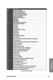
... Request Resources PCI Bus Assign Resources Console Output devices connect Console input devices connect Super IO Initialization USB initialization is started USB Reset USB Detect USB Enable Reserved for future AMI codes IDE initialization is started IDE Reset IDE Detect IDE Enable SCSI...USB hot plug PCI bus hot plug Clean-up of NVRAM Configuration Reset (reset of NVRAM settings) Reserved for future AMI codes CPU initialization error System Agent initialization error PCH initialization error Some of Resources No Space for Legacy Option ROM (continued on the next page) Chapter 1 ASUS X99-A/USB...
... Request Resources PCI Bus Assign Resources Console Output devices connect Console input devices connect Super IO Initialization USB initialization is started USB Reset USB Detect USB Enable Reserved for future AMI codes IDE initialization is started IDE Reset IDE Detect IDE Enable SCSI...USB hot plug PCI bus hot plug Clean-up of NVRAM Configuration Reset (reset of NVRAM settings) Reserved for future AMI codes CPU initialization error System Agent initialization error PCH initialization error Some of Resources No Space for Legacy Option ROM (continued on the next page) Chapter 1 ASUS X99-A/USB...

User Guide
Page 47
... DVD. • The SATAEXPRESS_1 connector can create a RAID 0, 1, 5, and 10 configuration with the Intel® Rapid Storage Technology through the onboard Intel® X99 chipset. Intel® X99 Serial ATA 6 Gb/s connectors (7-pin SATA6G_12, SATA6G_34, SATA6G_5, SATA6G_6/SATAEXPRESS, SATA6G_78, SATA6G_910) These connectors connect to chipset behavior, the SATA6G_78 and SATA6G_910 ports (black... to section 3.6.3 PCH Storage Configuration for details. • Before creating a RAID set, refer to the manual bundled in the BIOS to [AHCI Mode] by default. ASUS X99-A/USB 3.1 1-31
... DVD. • The SATAEXPRESS_1 connector can create a RAID 0, 1, 5, and 10 configuration with the Intel® Rapid Storage Technology through the onboard Intel® X99 chipset. Intel® X99 Serial ATA 6 Gb/s connectors (7-pin SATA6G_12, SATA6G_34, SATA6G_5, SATA6G_6/SATAEXPRESS, SATA6G_78, SATA6G_910) These connectors connect to chipset behavior, the SATA6G_78 and SATA6G_910 ports (black... to section 3.6.3 PCH Storage Configuration for details. • Before creating a RAID set, refer to the manual bundled in the BIOS to [AHCI Mode] by default. ASUS X99-A/USB 3.1 1-31
User Guide
Page 49
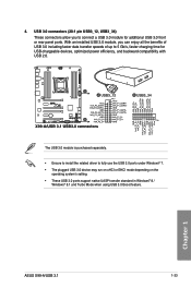
... Gb/s, faster charging time for additional USB 3.0 front or rear panel ports. With an installed USB 3.0 module, you to fully use the USB 3.0 ports under Windows® 7. • The plugged USB 3.0 device may run on xHCI or...USB 3.0 ports support native UASP transfer standard in Windows® 8 / Windows® 8.1 and Turbo Mode when using USB 3.0 Boost feature. The USB 3.0 module is purchased separately. • Ensure to install the related driver to connect a USB 3.0 module for USB-chargeable devices, optimized power efficiency, and backward compatibility with USB 2.0. ASUS X99-A/USB...
... Gb/s, faster charging time for additional USB 3.0 front or rear panel ports. With an installed USB 3.0 module, you to fully use the USB 3.0 ports under Windows® 7. • The plugged USB 3.0 device may run on xHCI or...USB 3.0 ports support native UASP transfer standard in Windows® 8 / Windows® 8.1 and Turbo Mode when using USB 3.0 Boost feature. The USB 3.0 module is purchased separately. • Ensure to install the related driver to connect a USB 3.0 module for USB-chargeable devices, optimized power efficiency, and backward compatibility with USB 2.0. ASUS X99-A/USB...
User Guide
Page 51
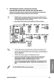
... CPU_FAN connector supports the CPU fan of maximum 1A (12 W) fan power. • The CPU_FAN, CHA_FAN, and EXT_FAN connectors support the ASUS FAN Xpert 3 feature on X99 platform. • The EXT_FAN connector supports 2 of 5 thermal sensor sources. • The CPU fan connector detects the type of the ...8226; Ensure that the black wire of each cable matches the ground pin of CPU fan installed and automatically switches the control modes. 6. ASUS X99-A/USB 3.1 1-35 The FAN EXTENSION CARD is securely installed to Advanced Mode > Monitor > CPU Q-Fan Control item in BIOS. To set these...
... CPU_FAN connector supports the CPU fan of maximum 1A (12 W) fan power. • The CPU_FAN, CHA_FAN, and EXT_FAN connectors support the ASUS FAN Xpert 3 feature on X99 platform. • The EXT_FAN connector supports 2 of 5 thermal sensor sources. • The CPU fan connector detects the type of the ...8226; Ensure that the black wire of each cable matches the ground pin of CPU fan installed and automatically switches the control modes. 6. ASUS X99-A/USB 3.1 1-35 The FAN EXTENSION CARD is securely installed to Advanced Mode > Monitor > CPU Q-Fan Control item in BIOS. To set these...

User Guide
Page 53
The system power LED lights up or flashes when data is read from or written to this connector. ASUS X99-A/USB 3.1 1-37 Chapter 1 System panel connector (20-8 pin PANEL) This connector supports several chassis-mounted functions. • System power LED (2-pin PLED) This 2-pin connector is ...
The system power LED lights up or flashes when data is read from or written to this connector. ASUS X99-A/USB 3.1 1-37 Chapter 1 System panel connector (20-8 pin PANEL) This connector supports several chassis-mounted functions. • System power LED (2-pin PLED) This 2-pin connector is ...

User Guide
Page 55
... is for the add-on Thunderbolt I /O card that allows you to connect up to monitor the temperature of your motherboard's critical components and connected devices. ASUS X99-A/USB 3.1 1-39 Chapter 1 11. The add-on Thunderbolt I /O card and Thunderbolt cables are purchased separately. 12. The thermistor cable is for the thermistor cable that supports...
... is for the add-on Thunderbolt I /O card that allows you to connect up to monitor the temperature of your motherboard's critical components and connected devices. ASUS X99-A/USB 3.1 1-39 Chapter 1 11. The add-on Thunderbolt I /O card and Thunderbolt cables are purchased separately. 12. The thermistor cable is for the thermistor cable that supports...

User Guide
Page 57
...'s high-definition audio capability. • If you want to connect a high-definition or an AC'97 front panel audio module to [HD] or [AC97]. Chapter 1 ASUS X99-A/USB 3.1 1-41 Front panel audio connector (10-1 pin AAFP) This connector is for a chassis-mounted front panel audio I /O module cable to this connector, set the Front...
...'s high-definition audio capability. • If you want to connect a high-definition or an AC'97 front panel audio module to [HD] or [AC97]. Chapter 1 ASUS X99-A/USB 3.1 1-41 Front panel audio connector (10-1 pin AAFP) This connector is for a chassis-mounted front panel audio I /O module cable to this connector, set the Front...

User Guide
Page 59
The motherboard layout may vary with models, but the installation steps are for all models. 1. Place the motherboard into the chassis, ensuring that its rear I/O ports are aligned to the chassis rear I /O panel. Chapter 2: Basic installation Basic installation 2.1 Building your PC system 2 2.1.1 Motherboard installation The diagrams in this section are the same for reference only. Chapter 2 ASUS X99-A/USB 3.1 2-1 Install the ASUS Q-Shield to the chassis' rear I /O panel. 2.
The motherboard layout may vary with models, but the installation steps are for all models. 1. Place the motherboard into the chassis, ensuring that its rear I/O ports are aligned to the chassis rear I /O panel. Chapter 2: Basic installation Basic installation 2.1 Building your PC system 2 2.1.1 Motherboard installation The diagrams in this section are the same for reference only. Chapter 2 ASUS X99-A/USB 3.1 2-1 Install the ASUS Q-Shield to the chassis' rear I /O panel. 2.


