
Vintage2-PH1 User''s Manual for English Edition
Page 7
.... Operation safety • Before installing devices into the system, carefully read all cables are correctly connected and the power cables are connected. • If the power supply is incorrectly replaced. Place the product on a stable surface. • If you detect any area where it by... retailer. If you encounter technical problems with the package. • Before using the product, make sure all the documentation that the power cables for the devices are unplugged before relocating the system. • When adding or removing devices to or from connectors, slots, ...
.... Operation safety • Before installing devices into the system, carefully read all cables are correctly connected and the power cables are connected. • If the power supply is incorrectly replaced. Place the product on a stable surface. • If you detect any area where it by... retailer. If you encounter technical problems with the package. • Before using the product, make sure all the documentation that the power cables for the devices are unplugged before relocating the system. • When adding or removing devices to or from connectors, slots, ...

Vintage2-PH1 User''s Manual for English Edition
Page 10
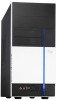
Support CD 4. Cable • AC power cable 3. User guide x Item description 1. ASUS Vintage2-PH1 barebone system with • ASUS motherboard • 300 W PFC power supply unit • ASUS chassis 2. System package contents Check your Vintage2-PH1 system package for the following items. If any of the items is damaged or missing, contact your retailer immediately.
Support CD 4. Cable • AC power cable 3. User guide x Item description 1. ASUS Vintage2-PH1 barebone system with • ASUS motherboard • 300 W PFC power supply unit • ASUS chassis 2. System package contents Check your Vintage2-PH1 system package for the following items. If any of the items is damaged or missing, contact your retailer immediately.

Vintage2-PH1 User''s Manual for English Edition
Page 14
... mouse. 4. This switch allows you to adjust the system input voltage according to the voltage supply in your area. 1.3 Rear panel The system rear panel includes the power connector and several I/O ports that conforms with serial specification. 1-4 Chapter 1: System introduction... 4 5 6 7 15 16 8 17 9 REAR S P K SIDE S P K C T R BASS LINE IN FRONT MIC IN 10 18 11 12 19 13 1. Power connector. Serial port . This connector is for a PS/2 keyboard. 5. See the "Voltage selector" section on page 1-6 before adjusting this switch. 3. PS/2 mouse port. Voltage ...
... mouse. 4. This switch allows you to adjust the system input voltage according to the voltage supply in your area. 1.3 Rear panel The system rear panel includes the power connector and several I/O ports that conforms with serial specification. 1-4 Chapter 1: System introduction... 4 5 6 7 15 16 8 17 9 REAR S P K SIDE S P K C T R BASS LINE IN FRONT MIC IN 10 18 11 12 19 13 1. Power connector. Serial port . This connector is for a PS/2 keyboard. 5. See the "Voltage selector" section on page 1-6 before adjusting this switch. 3. PS/2 mouse port. Voltage ...

Vintage2-PH1 User''s Manual for English Edition
Page 15
...port. Center/Subwoofer port (gray). VGA port. Microphone port (pink). This vent is for the PSU fan that provides ventilation inside the power supply unit. 15. This 6-pin IEEE 1394 port provides high-speed connectivity for connecting USB 2.0 devices. 9. Remove these covers when installing expansion... Speaker Out • Center/Subwoofer 8-channel Line In Front Speaker Out Mic In Rear Speaker Out Side Speaker Out Center/Subwoofer ASUS Vintage2-PH1 1-5 Expansion slot covers. Refer to a Local Area Network (LAN) through a network hub. 18. This port connects the side...
...port. Center/Subwoofer port (gray). VGA port. Microphone port (pink). This vent is for the PSU fan that provides ventilation inside the power supply unit. 15. This 6-pin IEEE 1394 port provides high-speed connectivity for connecting USB 2.0 devices. 9. Remove these covers when installing expansion... Speaker Out • Center/Subwoofer 8-channel Line In Front Speaker Out Mic In Rear Speaker Out Side Speaker Out Center/Subwoofer ASUS Vintage2-PH1 1-5 Expansion slot covers. Refer to a Local Area Network (LAN) through a network hub. 18. This port connects the side...

Vintage2-PH1 User''s Manual for English Edition
Page 16
If the voltage supply in your area. Voltage selector The PSU has a 115 V/230 V voltage selector switch located beside the power connector. Use this switch to select the appropriate system input voltage according to 115V in a 230V environment or 230V in your area is 100-127 V, set this switch to 115 V. If the voltage supply in your area is 200-240 V, set this switch to 230 V. 115V/230V Voltage selector Setting the switch to the voltage supply in a 115V environment will seriously damage the system! 1-6 Chapter 1: System introduction
If the voltage supply in your area. Voltage selector The PSU has a 115 V/230 V voltage selector switch located beside the power connector. Use this switch to select the appropriate system input voltage according to 115V in a 230V environment or 230V in your area is 100-127 V, set this switch to 115 V. If the voltage supply in your area is 200-240 V, set this switch to 230 V. 115V/230V Voltage selector Setting the switch to the voltage supply in a 115V environment will seriously damage the system! 1-6 Chapter 1: System introduction

Vintage2-PH1 User''s Manual for English Edition
Page 17
Floppy disk drive bay 5. CPU socket 7. ASUS motherboard 9. The installed components are labeled for instructions on installing additional system components. 5 2 13 PWR_FAN PS/2KBMS T: Mouse B: Keyboard COM1 ATX12V LGA775 6 ...I/O F_PANEL 3 1 4 1. DIMM sockets 8. PCI Express x16 slot 11. Front panel cover 2. 5.25-inch optical drive bays 3. Power supply unit 6. Hard disk drive bay 4. PCI Express x1 slot 13. Metal bracket lock ASUS Vintage2-PH1 1-7 Chassis fan 10. PCI slots 12. 1.4 Internal components The illustration below is the internal view of the system...
Floppy disk drive bay 5. CPU socket 7. ASUS motherboard 9. The installed components are labeled for instructions on installing additional system components. 5 2 13 PWR_FAN PS/2KBMS T: Mouse B: Keyboard COM1 ATX12V LGA775 6 ...I/O F_PANEL 3 1 4 1. DIMM sockets 8. PCI Express x16 slot 11. Front panel cover 2. 5.25-inch optical drive bays 3. Power supply unit 6. Hard disk drive bay 4. PCI Express x1 slot 13. Metal bracket lock ASUS Vintage2-PH1 1-7 Chassis fan 10. PCI slots 12. 1.4 Internal components The illustration below is the internal view of the system...

Vintage2-PH1 User''s Manual for English Edition
Page 20
... install components into the system. • Use a grounded wrist strap or touch a safely grounded object or a metal object, such as the power supply case, before installing any component, place it on them. • Whenever you plan to install in the system. Basic components to indicate that ...touching the ICs on a grounded antistatic pad or in the bag that came with an onboard standby power LED. DDR Dual Inline Memory Module (DIMM) 3. Unplug the power cable from the power outlet and make sure that you have all the components you uninstall any system component. ® Onboard...
... install components into the system. • Use a grounded wrist strap or touch a safely grounded object or a metal object, such as the power supply case, before installing any component, place it on them. • Whenever you plan to install in the system. Basic components to indicate that ...touching the ICs on a grounded antistatic pad or in the bag that came with an onboard standby power LED. DDR Dual Inline Memory Module (DIMM) 3. Unplug the power cable from the power outlet and make sure that you have all the components you uninstall any system component. ® Onboard...

Vintage2-PH1 User''s Manual for English Edition
Page 27
... the break on the socket. 1 2 DDR2 DIMM notch 1 Unlocked retaining clip A DDR2 DIMM is properly seated. Firmly insert the DIMM into a socket to unplug the power supply before adding or removing DIMMs or other system components. Unlock a DDR2 DIMM socket by pressing the retaining clips outward. 2. Locked Retaining Clip 2.5.3 Removing a DDR2 DIMM... such that it flips out with your fingers when pressing the retaining clips. 2.5.2 Installing a DDR2 DIMM Make sure to avoid damaging the DIMM. 3. ASUS Vintage2-PH1 2-9
... the break on the socket. 1 2 DDR2 DIMM notch 1 Unlocked retaining clip A DDR2 DIMM is properly seated. Firmly insert the DIMM into a socket to unplug the power supply before adding or removing DIMMs or other system components. Unlock a DDR2 DIMM socket by pressing the retaining clips outward. 2. Locked Retaining Clip 2.5.3 Removing a DDR2 DIMM... such that it flips out with your fingers when pressing the retaining clips. 2.5.2 Installing a DDR2 DIMM Make sure to avoid damaging the DIMM. 3. ASUS Vintage2-PH1 2-9

Vintage2-PH1 User''s Manual for English Edition
Page 31
Follow these steps to install a new optical drive. Connect a power cable from the power supply to the power connector at the back of the bay. 3 4 4 5. Insert the optical drive into the upper 5.25-inch drive bay and carefully push the optical drive into ... you wish to install an optical drive. 1. Secure the optical drive with two screws on the bay as shown. 4. Audio cable IDE ribbon cable Power cable ASUS Vintage2-PH1 2-13 Place the chassis upright. 2. Connect one end of the audio cable to the IDE interface at the back of the optical drive, matching...
Follow these steps to install a new optical drive. Connect a power cable from the power supply to the power connector at the back of the bay. 3 4 4 5. Insert the optical drive into the upper 5.25-inch drive bay and carefully push the optical drive into ... you wish to install an optical drive. 1. Secure the optical drive with two screws on the bay as shown. 4. Audio cable IDE ribbon cable Power cable ASUS Vintage2-PH1 2-13 Place the chassis upright. 2. Connect one end of the audio cable to the IDE interface at the back of the optical drive, matching...

Vintage2-PH1 User''s Manual for English Edition
Page 34
...end of the Serial ATA cable to the SATA connector at the back of the drive, then connect the other end to the 4-pin (male) power connector at the back, use both 4-pin and 15-pin connectors at the back of the Serial ATA connectors. 6. See page 4-6 for the location... of the drive. Serial ATA power Serial ATA cable cable 5. DO NOT use either the 15-pin SATA power adapter plug OR the legacy 4-pin power connector. Connect a 15-pin Serial ATA power plug from the power supply unit to keep the system from the power supply unit to a Serial ATA connector on the motherboard....
...end of the Serial ATA cable to the SATA connector at the back of the drive, then connect the other end to the 4-pin (male) power connector at the back, use both 4-pin and 15-pin connectors at the back of the Serial ATA connectors. 6. See page 4-6 for the location... of the drive. Serial ATA power Serial ATA cable cable 5. DO NOT use either the 15-pin SATA power adapter plug OR the legacy 4-pin power connector. Connect a 15-pin Serial ATA power plug from the power supply unit to keep the system from the power supply unit to a Serial ATA connector on the motherboard....

Vintage2-PH1 User''s Manual for English Edition
Page 35
...disk drive, make sure to configure your hard disk drive as Slave. 3. Refer to the power connector at the back of the previous section. 2. Connect a 4-pin power plug from the power supply unit to the HDD documentation on the second (Slave) IDE hard disk drive. 5. To install an ...hard disk drive: 1. IDE ribbon cable Power cable • If you install two IDE hard disk drives, connect the black interface of the IDE ribbon cable to the IDE connector on the motherboard. Connect the gray interface of the PRI_IDE connector. ASUS Vintage2-PH1 2-17 See page 4-4 for the location...
...disk drive, make sure to configure your hard disk drive as Slave. 3. Refer to the power connector at the back of the previous section. 2. Connect a 4-pin power plug from the power supply unit to the HDD documentation on the second (Slave) IDE hard disk drive. 5. To install an ...hard disk drive: 1. IDE ribbon cable Power cable • If you install two IDE hard disk drives, connect the black interface of the IDE ribbon cable to the IDE connector on the motherboard. Connect the gray interface of the PRI_IDE connector. ASUS Vintage2-PH1 2-17 See page 4-4 for the location...

Vintage2-PH1 User''s Manual for English Edition
Page 36
... drive with the holes on the motherboard. 6. Connect a power cable from the power supply unit to the signal connector at the back of the floppy disk drive. 2-18 Chapter 2: Basic installation Remove the front panel cover. Power cable Floppy ribbon cable 5. Carefully insert the floppy ...2.9 Installing a floppy disk drive The Vintage2-PH1 system comes with one 3.25-inch drive bay for a floppy disk drive. To install a floppy disk drive: 1. Connect the floppy disk drive signal cable to the power connector at the back of section "2.3 Removing the...
... drive with the holes on the motherboard. 6. Connect a power cable from the power supply unit to the signal connector at the back of the floppy disk drive. 2-18 Chapter 2: Basic installation Remove the front panel cover. Power cable Floppy ribbon cable 5. Carefully insert the floppy ...2.9 Installing a floppy disk drive The Vintage2-PH1 system comes with one 3.25-inch drive bay for a floppy disk drive. To install a floppy disk drive: 1. Connect the floppy disk drive signal cable to the power connector at the back of section "2.3 Removing the...

Vintage2-PH1 User''s Manual for English Edition
Page 37
LED cables Reset button IDE LED Power Switch Power LED Power LED ® System panel connector F_PANEL PWRSW PWRLED GND PWR PWR_LEDPWR_LED+ Reset Ground IDE_LEDIDE_LED+ RESET IDE LED * Requires an ATX power supply. You must re-connect these cables before you were installing components. 2.10 Re-connecting cables You may have disconnected some cables when you replace the chassis cover. ASUS Vintage2-PH1 2-19 Connect the reset button, power switch, power LED, and HDD LED cables to their respective leads in the system panel connector on the motherboard.
LED cables Reset button IDE LED Power Switch Power LED Power LED ® System panel connector F_PANEL PWRSW PWRLED GND PWR PWR_LEDPWR_LED+ Reset Ground IDE_LEDIDE_LED+ RESET IDE LED * Requires an ATX power supply. You must re-connect these cables before you were installing components. 2.10 Re-connecting cables You may have disconnected some cables when you replace the chassis cover. ASUS Vintage2-PH1 2-19 Connect the reset button, power switch, power LED, and HDD LED cables to their respective leads in the system panel connector on the motherboard.

Vintage2-PH1 User''s Manual for English Edition
Page 58
...64257;rmly until the connectors completely fit. Doing so will damage the motherboard! ATX power connectors (24-pin ATXPWR, 4-pin ATX12V) These connectors are for USB 2.0 ports. ATX power connectors ® EATXPWR ATX12V GND +12V DC +3 Volts +12 Volts +12 Volts... Volts +5 Volts -5 Volts Ground Ground Ground PSON# Ground -12 Volts +3 Volts 4-6 Chapter 4: Motherboard info 5. The plugs from the power supply are for ATX power supply plugs. The USB module is purchased separately. 6. USB connectors (10-1 pin USB56, USB78) These connectors are designed to fit these ...
...64257;rmly until the connectors completely fit. Doing so will damage the motherboard! ATX power connectors (24-pin ATXPWR, 4-pin ATX12V) These connectors are for USB 2.0 ports. ATX power connectors ® EATXPWR ATX12V GND +12V DC +3 Volts +12 Volts +12 Volts... Volts +5 Volts -5 Volts Ground Ground Ground PSON# Ground -12 Volts +3 Volts 4-6 Chapter 4: Motherboard info 5. The plugs from the power supply are for ATX power supply plugs. The USB module is purchased separately. 6. USB connectors (10-1 pin USB56, USB78) These connectors are designed to fit these ...

Vintage2-PH1 User''s Manual for English Edition
Page 62
...up when you to hear system beeps and warnings. ® Speaker out connector SPEAKER +5V GND GND Speak Out 1 14. Pressing the power button turns the system ON or puts the system in sleep mode. 4-10 Chapter 4: Motherboard info System front panel connector (10-1 pin ... PWRSW PWRLED GND PWR PWR_LEDPWR_LED+ Reset Ground IDE_LEDIDE_LED+ RESET IDE LED * Requires an ATX power supply. • Power/Soft-off button (Black 2-pin PWRSW) This connector is for the system power LED. Pressing the power switch for more than four seconds while the system is ON turns the system OFF. •...
...up when you to hear system beeps and warnings. ® Speaker out connector SPEAKER +5V GND GND Speak Out 1 14. Pressing the power button turns the system ON or puts the system in sleep mode. 4-10 Chapter 4: Motherboard info System front panel connector (10-1 pin ... PWRSW PWRLED GND PWR PWR_LEDPWR_LED+ Reset Ground IDE_LEDIDE_LED+ RESET IDE LED * Requires an ATX power supply. • Power/Soft-off button (Black 2-pin PWRSW) This connector is for the system power LED. Pressing the power switch for more than four seconds while the system is ON turns the system OFF. •...

Vintage2-PH1 User''s Manual for English Edition
Page 95
...this parameter allows you to turn on the system through a PCI Express LAN card. This feature requires an ATX power supply that provides at least 1A on the +5VSB lead. Power On By PCI Devices [Disabled] When set to [Enabled], this parameter allows you to turn on the system ...through a PCI LAN or modem card. This feature requires an ATX power supply that provides at least 1A on the +5VSB lead. Configuration options: [Disabled] [Enabled] ASUS Vintage2-PH1 5-...
...this parameter allows you to turn on the system through a PCI Express LAN card. This feature requires an ATX power supply that provides at least 1A on the +5VSB lead. Power On By PCI Devices [Disabled] When set to [Enabled], this parameter allows you to turn on the system ...through a PCI LAN or modem card. This feature requires an ATX power supply that provides at least 1A on the +5VSB lead. Configuration options: [Disabled] [Enabled] ASUS Vintage2-PH1 5-...