
E787 MANUAL TERMINATOR English
Page 2
...owners' benefit, without the express written permission of ASUSTeK COMPUTER INC. ("ASUS"). Product Name: Terminator Barebone System Manual Revision: 1.01 E787 Release Date: May 2001 2 Manual updates are represented by ASUS; ASUS PROVIDES THIS MANUAL "AS IS" WITHOUT WARRANTY OF ANY KIND, EITHER ...transmitted, transcribed, stored in a retrieval system, or translated into any language in the manual revision number. IN NO EVENT SHALL ASUS, ITS DIRECTORS, OFFICERS, EMPLOYEES OR AGENTS BE LIABLE FOR ANY INDIRECT, SPECIAL, INCIDENTAL, OR CONSEQUENTIAL DAMAGES (INCLUDING DAMAGES FOR LOSS...
...owners' benefit, without the express written permission of ASUSTeK COMPUTER INC. ("ASUS"). Product Name: Terminator Barebone System Manual Revision: 1.01 E787 Release Date: May 2001 2 Manual updates are represented by ASUS; ASUS PROVIDES THIS MANUAL "AS IS" WITHOUT WARRANTY OF ANY KIND, EITHER ...transmitted, transcribed, stored in a retrieval system, or translated into any language in the manual revision number. IN NO EVENT SHALL ASUS, ITS DIRECTORS, OFFICERS, EMPLOYEES OR AGENTS BE LIABLE FOR ANY INDIRECT, SPECIAL, INCIDENTAL, OR CONSEQUENTIAL DAMAGES (INCLUDING DAMAGES FOR LOSS...

E787 MANUAL TERMINATOR English
Page 3
... +886-2-2890-7123 Tel (Chinese): +886-2-2890-7113 Fax: +886-2-2893-7775 Email: tsd@asus.com.tw Newsgroup: news2.asus.com.tw WWW: www.asus.com.tw FTP: ftp.asus.com.tw/pub/ASUS ASUS COMPUTER INTERNATIONAL (America) Marketing Address: Fax: Email: 6737 Mowry Avenue, Mowry Business Center, Building ...2 Newark, CA 94560, USA +1-510-608-4555 info-usa@asus.com.tw Technical Support Fax: +1-510-608-4555 BBS: +1-510-739-3774 Email: tsd@asus.com WWW: www.asus.com FTP: ftp.asus.com.tw/pub/ASUS ASUS COMPUTER GmbH (Europe) Marketing Address: Fax: Email: Harkortstr. 25, ...
... +886-2-2890-7123 Tel (Chinese): +886-2-2890-7113 Fax: +886-2-2893-7775 Email: tsd@asus.com.tw Newsgroup: news2.asus.com.tw WWW: www.asus.com.tw FTP: ftp.asus.com.tw/pub/ASUS ASUS COMPUTER INTERNATIONAL (America) Marketing Address: Fax: Email: 6737 Mowry Avenue, Mowry Business Center, Building ...2 Newark, CA 94560, USA +1-510-608-4555 info-usa@asus.com.tw Technical Support Fax: +1-510-608-4555 BBS: +1-510-739-3774 Email: tsd@asus.com WWW: www.asus.com FTP: ftp.asus.com.tw/pub/ASUS ASUS COMPUTER GmbH (Europe) Marketing Address: Fax: Email: Harkortstr. 25, ...

E787 MANUAL TERMINATOR English
Page 4
These limits are designed to assure compliance with FCC regulations. Canadian Department of Communications Statement This digital apparatus does not exceed the Class B limits for help. Safeguards FCC/CDC Statements Federal Communications Commission Statement This device complies with Canadian ICES-003. 4 WARNING! However, there is no guarantee that may not cause harmful interference, and • This device must accept any interference received including interference that interference will not occur in accordance with the limits for connection of Communications. ...
These limits are designed to assure compliance with FCC regulations. Canadian Department of Communications Statement This digital apparatus does not exceed the Class B limits for help. Safeguards FCC/CDC Statements Federal Communications Commission Statement This device complies with Canadian ICES-003. 4 WARNING! However, there is no guarantee that may not cause harmful interference, and • This device must accept any interference received including interference that interference will not occur in accordance with the limits for connection of Communications. ...
E787 MANUAL TERMINATOR English
Page 5
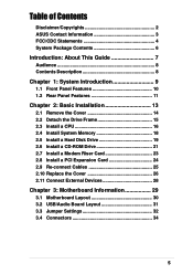
Table of Contents Disclaimer/Copyrights 2 ASUS Contact Information 3 FCC/CDC Statements 4 System Package Contents 6 Introduction: About This Guide 7 Audience 8 Contents Description 8 Chapter 1: System Introduction 9 1.1 Front Panel Features 10 1.2 Rear Panel Features ...
Table of Contents Disclaimer/Copyrights 2 ASUS Contact Information 3 FCC/CDC Statements 4 System Package Contents 6 Introduction: About This Guide 7 Audience 8 Contents Description 8 Chapter 1: System Introduction 9 1.1 Front Panel Features 10 1.2 Rear Panel Features ...

E787 MANUAL TERMINATOR English
Page 6
System Package Contents The following checklist enumerates the components included in the standard system package. 1) System Chassis 2) Motherboard 3) Switching Power Supply 4) 1.44MB Floppy Disk Drive 5) CD-ROM Drive (optional) 6) 56K PCI Modem Card (optional) 7) Support CD with Drivers and Utilities 8) Installation Guide NOTE If you need them. 6 It saves you a lot of time not having to hunt down components when you are assembling the system by yourself, make sure to prepare all the components before starting.
System Package Contents The following checklist enumerates the components included in the standard system package. 1) System Chassis 2) Motherboard 3) Switching Power Supply 4) 1.44MB Floppy Disk Drive 5) CD-ROM Drive (optional) 6) 56K PCI Modem Card (optional) 7) Support CD with Drivers and Utilities 8) Installation Guide NOTE If you need them. 6 It saves you a lot of time not having to hunt down components when you are assembling the system by yourself, make sure to prepare all the components before starting.

E787 MANUAL TERMINATOR English
Page 7
About This Guide ASUS Terminator Barebone System 7 Introduction You are reading the ASUS Terminator Barebone System Installation Guide. This guide provides general information and installation instructions about the Terminator Barebone System. "About This Guide" contains an introduction on the contents of this document that include target audience and chapter description.
About This Guide ASUS Terminator Barebone System 7 Introduction You are reading the ASUS Terminator Barebone System Installation Guide. This guide provides general information and installation instructions about the Terminator Barebone System. "About This Guide" contains an introduction on the contents of this document that include target audience and chapter description.

E787 MANUAL TERMINATOR English
Page 8
...This installation guide is intended for experienced users and integrators with hardware knowledge of this document that comes with the ASUS Terminator Barebone System.This chapter includes the motherboard layout, jumper settings, and connector locations. Contents Description This installation guide ..., and the internal features. 3. Chapter 1: System Introduction This chapter gives a general description of the ASUS Terminator barebone system. Chapter 3: Motherboard Information This chapter gives information about the CUSC motherboard that include target audience and chapter description. 2.
...This installation guide is intended for experienced users and integrators with hardware knowledge of this document that comes with the ASUS Terminator Barebone System.This chapter includes the motherboard layout, jumper settings, and connector locations. Contents Description This installation guide ..., and the internal features. 3. Chapter 1: System Introduction This chapter gives a general description of the ASUS Terminator barebone system. Chapter 3: Motherboard Information This chapter gives information about the CUSC motherboard that include target audience and chapter description. 2.

E787 MANUAL TERMINATOR English
Page 9
It includes introduction on the front and rear panel features, and the internal features. ASUS Terminator Barebone System 9 System Introduction Chapter 1 This chapter gives a general description of the ASUS Terminator barebone system.
It includes introduction on the front and rear panel features, and the internal features. ASUS Terminator Barebone System 9 System Introduction Chapter 1 This chapter gives a general description of the ASUS Terminator barebone system.

E787 MANUAL TERMINATOR English
Page 10
... items and may not come installed in the ASUS TriOptix form factor chassis. The following figures show the connectors as in the above figure. 10 Chapter 1: System Introduction 1.1 Front Panel Features The ASUS Terminator barebone system is a door that covers accessible ...I/O features that include two USB connectors (Ports 2&3), a headphone connector, and a microphone connector. Push the dotted area of the ASUS CUSC motherboard, a power supply, and a floppy ...
... items and may not come installed in the ASUS TriOptix form factor chassis. The following figures show the connectors as in the above figure. 10 Chapter 1: System Introduction 1.1 Front Panel Features The ASUS Terminator barebone system is a door that covers accessible ...I/O features that include two USB connectors (Ports 2&3), a headphone connector, and a microphone connector. Push the dotted area of the ASUS CUSC motherboard, a power supply, and a floppy ...

E787 MANUAL TERMINATOR English
Page 11
... to 115V in your area. Setting the switch to the voltage supply in a 230V environment will seriously damage the system. ASUS Terminator Barebone System 11 1.2 Rear Panel Features The rear panel of the ASUS Terminator barebone system includes the standard PC99 I/O connectors for external devices, power supply socket, and optional modem connectors. Game/MIDI...
... to 115V in your area. Setting the switch to the voltage supply in a 230V environment will seriously damage the system. ASUS Terminator Barebone System 11 1.2 Rear Panel Features The rear panel of the ASUS Terminator barebone system includes the standard PC99 I/O connectors for external devices, power supply socket, and optional modem connectors. Game/MIDI...

E787 MANUAL TERMINATOR English
Page 12
Two 5.25" 3.5" HDD 3.5" Floppy Drive Bays Drive Bay Drive Power Supply Modem Card Motherboard USB/audio Board 12 Chapter 1: System Introduction You will see here the standard components that come already installed in the system and the places where you remove the cover and flip out the drive frame. 1.3 Internal Features The figure below shows the internal view of the system when you can install the other required components to get the system running.
Two 5.25" 3.5" HDD 3.5" Floppy Drive Bays Drive Bay Drive Power Supply Modem Card Motherboard USB/audio Board 12 Chapter 1: System Introduction You will see here the standard components that come already installed in the system and the places where you remove the cover and flip out the drive frame. 1.3 Internal Features The figure below shows the internal view of the system when you can install the other required components to get the system running.

E787 MANUAL TERMINATOR English
Page 13
Basic Installation ASUS Terminator Barebone System 13 Chapter 2 This chapter tells how to install components into the barebone system through illustrated step-by-step instructions.
Basic Installation ASUS Terminator Barebone System 13 Chapter 2 This chapter tells how to install components into the barebone system through illustrated step-by-step instructions.

E787 MANUAL TERMINATOR English
Page 14
You don't have to push on the CDROM area with your thumbs while holding the front panel, place your hand underneath the front panel and push up . 3. Locking Tab TIP Another way to release the cover is secured by a thumbscrew located on the top rear edge of the front panel. Follow these steps to release the cover. Then lift it up the locking tab that secures the panel to the chassis. Turn the captive thumbscrew counter-clockwise to remove the chassis cover. 1. Place your other hand on the rear panel. 2.1 Remove the Cover The chassis cover is to remove the thumbscrew ...
You don't have to push on the CDROM area with your thumbs while holding the front panel, place your hand underneath the front panel and push up . 3. Locking Tab TIP Another way to release the cover is secured by a thumbscrew located on the top rear edge of the front panel. Follow these steps to release the cover. Then lift it up the locking tab that secures the panel to the chassis. Turn the captive thumbscrew counter-clockwise to remove the chassis cover. 1. Place your other hand on the rear panel. 2.1 Remove the Cover The chassis cover is to remove the thumbscrew ...

E787 MANUAL TERMINATOR English
Page 15
... chassis when installing components. 2. 2.2 Detach the Drive Frame After removing the chassis cover, detach the disk drive frame to access the components beneath it outward. ASUS Terminator Barebone System 15 It is attached to detach the drive frame. 1. Follow these steps to the main chassis. Carefully lay the drive frame alongside the...
... chassis when installing components. 2. 2.2 Detach the Drive Frame After removing the chassis cover, detach the disk drive frame to access the components beneath it outward. ASUS Terminator Barebone System 15 It is attached to detach the drive frame. 1. Follow these steps to the main chassis. Carefully lay the drive frame alongside the...
E787 MANUAL TERMINATOR English
Page 16
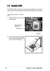
CPU Fan Connector (CPU_FAN) CPU Socket 370 2. Follow these steps to a 90°-100° angle. Socket Pin 1 16 Chapter 2: Basic Installation 2.3 Install a CPU The ASUS CUSC motherboard that comes installed in the chassis has a Socket 370 that supports an Intel Pentium III/Celeron processor. Locate the CPU socket on the motherboard. Unlock the socket by pressing the lever sideways then lifting it up to install a CPU. 1.
CPU Fan Connector (CPU_FAN) CPU Socket 370 2. Follow these steps to a 90°-100° angle. Socket Pin 1 16 Chapter 2: Basic Installation 2.3 Install a CPU The ASUS CUSC motherboard that comes installed in the chassis has a Socket 370 that supports an Intel Pentium III/Celeron processor. Locate the CPU socket on the motherboard. Unlock the socket by pressing the lever sideways then lifting it up to install a CPU. 1.

E787 MANUAL TERMINATOR English
Page 17
ASUS Terminator Barebone System 17 The lever clicks in place. Position the CPU above the socket such that its orientation or check for bent pins. Carefully insert ...
ASUS Terminator Barebone System 17 The lever clicks in place. Position the CPU above the socket such that its orientation or check for bent pins. Carefully insert ...

E787 MANUAL TERMINATOR English
Page 18
Locate the DIMM sockets on the socket. Unlock a DIMM socket by pressing the retaining clips outward. DIMM Notch Socket Break CAUTION! 2.4 Install System Memory The motherboard includes two 168-pin Dual Inline Memory Module (DIMM) sockets. Firmly insert the DIMM in the socket until the retaining clips snap back in only one direction. Installed DIMM 18 Chapter 2: Basic Installation DIMM Sockets 2. DIMMs are keyed with notches so that the notches on the DIMM match the breaks on the motherboard. Align a DIMM on the socket such that they fit in place and the DIMM is properly ...
Locate the DIMM sockets on the socket. Unlock a DIMM socket by pressing the retaining clips outward. DIMM Notch Socket Break CAUTION! 2.4 Install System Memory The motherboard includes two 168-pin Dual Inline Memory Module (DIMM) sockets. Firmly insert the DIMM in the socket until the retaining clips snap back in only one direction. Installed DIMM 18 Chapter 2: Basic Installation DIMM Sockets 2. DIMMs are keyed with notches so that the notches on the DIMM match the breaks on the motherboard. Align a DIMM on the socket such that they fit in place and the DIMM is properly ...

E787 MANUAL TERMINATOR English
Page 19
...-inch bay. Secure the HDD with the holes on each side of the HDD bay location. Place the chassis upright. 2. HDD Component Side 3. HDD Screws ASUS Terminator Barebone System 19 Carefully push the HDD into the bay until its component side up, carefully insert the HDD into the 3.5-inch bay.
...-inch bay. Secure the HDD with the holes on each side of the HDD bay location. Place the chassis upright. 2. HDD Component Side 3. HDD Screws ASUS Terminator Barebone System 19 Carefully push the HDD into the bay until its component side up, carefully insert the HDD into the 3.5-inch bay.

E787 MANUAL TERMINATOR English
Page 20
Connect a power cable from the power supply to the power connector at the back of the HDD, matching the red stripe on the cable with the white connector labeled HDD. 6. Connect the other end of the HDD. 2.5 Install a Hard Disk Drive 5. Connect one end of the IDE hard disk ribbon cable to the IDE interface at the back of the IDE ribbon cable to Pin 1 Power Cable (HDD) 7. Use the cable with Pin 1 on the motherboard. Primary IDE Connector (IDE1) 20 Chapter 2: Basic Installation Red Stripe to the primary IDE connector (blue connector labeled IDE1) on the IDE Ribbon Cable ...
Connect a power cable from the power supply to the power connector at the back of the HDD, matching the red stripe on the cable with the white connector labeled HDD. 6. Connect the other end of the HDD. 2.5 Install a Hard Disk Drive 5. Connect one end of the IDE hard disk ribbon cable to the IDE interface at the back of the IDE ribbon cable to Pin 1 Power Cable (HDD) 7. Use the cable with Pin 1 on the motherboard. Primary IDE Connector (IDE1) 20 Chapter 2: Basic Installation Red Stripe to the primary IDE connector (blue connector labeled IDE1) on the IDE Ribbon Cable ...

E787 MANUAL TERMINATOR English
Page 21
Carefully push the CD-ROM drive into the upper 5.25-inch bay. 3. Insert the CD-ROM drive into the bay until its screw holes align with two screws on the bay as shown. 4. Place the chassis upright. 2. Refer to install a CD-ROM drive. 1. 2.6 Install a CD-ROM Drive A CD-ROM drive is an optional item in this section if you acquired a model without a CD-ROM. Secure the CD-ROM with the holes on each side of the bay. 5.25-inch Drive Bay CD-ROM Screws ASUS Terminator Barebone System 21 Follow these steps to the instructions in the Terminator barebone system.
Carefully push the CD-ROM drive into the upper 5.25-inch bay. 3. Insert the CD-ROM drive into the bay until its screw holes align with two screws on the bay as shown. 4. Place the chassis upright. 2. Refer to install a CD-ROM drive. 1. 2.6 Install a CD-ROM Drive A CD-ROM drive is an optional item in this section if you acquired a model without a CD-ROM. Secure the CD-ROM with the holes on each side of the bay. 5.25-inch Drive Bay CD-ROM Screws ASUS Terminator Barebone System 21 Follow these steps to the instructions in the Terminator barebone system.