E787 MANUAL TERMINATOR English
Page 5
Table of Contents Disclaimer/Copyrights 2 ASUS Contact Information 3 FCC/CDC Statements 4 System Package Contents 6 Introduction: About This Guide 7 Audience 8 Contents Description 8 Chapter 1: System Introduction 9 1.1 Front Panel Features 10 1.2 Rear Panel Features 11 Chapter 2: Basic Installation 13 2.1 Remove the Cover 14 2.2 Detach the Drive Frame 15 2.3 Install a CPU 16 2.4 Install System Memory 18 2.5 Install...
Table of Contents Disclaimer/Copyrights 2 ASUS Contact Information 3 FCC/CDC Statements 4 System Package Contents 6 Introduction: About This Guide 7 Audience 8 Contents Description 8 Chapter 1: System Introduction 9 1.1 Front Panel Features 10 1.2 Rear Panel Features 11 Chapter 2: Basic Installation 13 2.1 Remove the Cover 14 2.2 Detach the Drive Frame 15 2.3 Install a CPU 16 2.4 Install System Memory 18 2.5 Install...
E787 MANUAL TERMINATOR English
Page 16
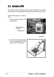
Unlock the socket by pressing the lever sideways then lifting it up to install a CPU. 1. Locate the CPU socket on the motherboard. CPU Fan Connector (CPU_FAN) CPU Socket 370 2. Follow these steps to a 90°-100° angle. Socket Pin 1 16 Chapter 2: Basic Installation 2.3 Install a CPU The ASUS CUSC motherboard that comes installed in the chassis has a Socket 370 that supports an Intel Pentium III/Celeron processor.
Unlock the socket by pressing the lever sideways then lifting it up to install a CPU. 1. Locate the CPU socket on the motherboard. CPU Fan Connector (CPU_FAN) CPU Socket 370 2. Follow these steps to a 90°-100° angle. Socket Pin 1 16 Chapter 2: Basic Installation 2.3 Install a CPU The ASUS CUSC motherboard that comes installed in the chassis has a Socket 370 that supports an Intel Pentium III/Celeron processor.

E787 MANUAL TERMINATOR English
Page 17
... the socket such that its orientation or check for bent pins. Carefully insert the CPU into the socket to prevent bending the pins and damaging the CPU. Socket Pin 1 5. CPU Fan Cable WARNING! If the CPU does not fit completely, check its notched or marked corner matches the Socket Pin ...to the 3-pin CPU_FAN connector on the motherboard. Connect the CPU fan cable to secure the CPU. ASUS Terminator Barebone System 17 The lever clicks in place. Refer to the socket. The CPU fits only in step 1. DO NOT force the CPU into the socket until it fits in place indicating that ...
... the socket such that its orientation or check for bent pins. Carefully insert the CPU into the socket to prevent bending the pins and damaging the CPU. Socket Pin 1 5. CPU Fan Cable WARNING! If the CPU does not fit completely, check its notched or marked corner matches the Socket Pin ...to the 3-pin CPU_FAN connector on the motherboard. Connect the CPU fan cable to secure the CPU. ASUS Terminator Barebone System 17 The lever clicks in place. Refer to the socket. The CPU fits only in step 1. DO NOT force the CPU into the socket until it fits in place indicating that ...

E787 MANUAL TERMINATOR English
Page 32
...Device Wake Up. Set these jumpers to +5V to allow wake up from S3 state (no power to allow wake up from S1 sleep state (CPU stopped; RAM refreshed; CUSC ® CUSC USB Device Wake Up USBPWR USBPWR1 12 +5VSB 23 +5V 32 Chapter 3: Motherboard Information RAM in ...reduced power mode). Set to +5VSB to CPU; power supply in slow refresh; 3.3 Jumper Settings The following jumper settings are for your reference in low power mode) using the connected USB devices. ...
...Device Wake Up. Set these jumpers to +5V to allow wake up from S3 state (no power to allow wake up from S1 sleep state (CPU stopped; RAM refreshed; CUSC ® CUSC USB Device Wake Up USBPWR USBPWR1 12 +5VSB 23 +5V 32 Chapter 3: Motherboard Information RAM in ...reduced power mode). Set to +5VSB to CPU; power supply in slow refresh; 3.3 Jumper Settings The following jumper settings are for your reference in low power mode) using the connected USB devices. ...


