
User Guide
Page 13
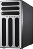
ASUS TS300-E8-RS4-C Product introduction Chapter 1 This chapter describes the general features of the server, including sections on front panel and rear panel specifications.
ASUS TS300-E8-RS4-C Product introduction Chapter 1 This chapter describes the general features of the server, including sections on front panel and rear panel specifications.

User Guide
Page 15
... x16 Link; The server supports Intel® LGA1150 Xeon® E3-1200 v3 processors with the latest technologies through the chipsets onboard. 1.3 System specifications The ASUS® TS300-E8-RS4-C is occupied) 2 x PCI-E x8 (Gen3 x8 Link) 1 x PCI-E x1 (Gen2 x1 Link), MIO support 1 x PCI-E x1 (Gen2 x1 Link) 2 x PCI 32-bit /33MHz 1 x PIKE...
... x16 Link; The server supports Intel® LGA1150 Xeon® E3-1200 v3 processors with the latest technologies through the chipsets onboard. 1.3 System specifications The ASUS® TS300-E8-RS4-C is occupied) 2 x PCI-E x8 (Gen3 x8 Link) 1 x PCI-E x1 (Gen2 x1 Link), MIO support 1 x PCI-E x1 (Gen2 x1 Link) 2 x PCI 32-bit /33MHz 1 x PIKE...

User Guide
Page 17
... four USB ports are located on the front panel. 1.4 Front panel features The barebone server displays a simple yet stylish front panel with easily accessible features. ASUS TS300-E8-RS4-C 1-5 Message LED HDD access LED Power LED Optical drive LAN1 LED LAN2 LED Locate LED Empty 5.25-inch bays 4-bay HDD cage Security lock Power...
... four USB ports are located on the front panel. 1.4 Front panel features The barebone server displays a simple yet stylish front panel with easily accessible features. ASUS TS300-E8-RS4-C 1-5 Message LED HDD access LED Power LED Optical drive LAN1 LED LAN2 LED Locate LED Empty 5.25-inch bays 4-bay HDD cage Security lock Power...

User Guide
Page 19
... if you need to use a floppy disk or a optical disc. *WARNING HAZARDOUS MOVING PARTS KEEP FINGERS AND OTHER BODY PARTS AWAY ASUS TS300-E8-RS4-C 1-7 Connect a USB floppy disk drive or a USB ODD to any system component. The barebone server does not include a floppy ...disk drive and an optical disc drive. SATA/SAS backplane board (first set , optional) 9. Expansion card locks 6. ASUS P9D-E/4L Server Board 4. 1.6 Internal features The barebone server includes the basic components as shown. 1 6 2 9 3 7 4 5 8 1. 550W 80PLUS Gold...
... if you need to use a floppy disk or a optical disc. *WARNING HAZARDOUS MOVING PARTS KEEP FINGERS AND OTHER BODY PARTS AWAY ASUS TS300-E8-RS4-C 1-7 Connect a USB floppy disk drive or a USB ODD to any system component. The barebone server does not include a floppy ...disk drive and an optical disc drive. SATA/SAS backplane board (first set , optional) 9. Expansion card locks 6. ASUS P9D-E/4L Server Board 4. 1.6 Internal features The barebone server includes the basic components as shown. 1 6 2 9 3 7 4 5 8 1. 550W 80PLUS Gold...

User Guide
Page 21
1.7.2 Rear panel LEDs Status OFF GREEN BLINKING ACT/LINK LED Description No link Linked Data activity ACT/LINK LED SPEED LED ACT/LINK LED SPEED LED ACT/LINK LED SPEED LED ACT/LINK LED SPEED LED Status OFF ORANGE GREEN SPEED LED Description 10 Mbps connection 100 Mbps connection 1 Gbps connection ASUS TS300-E8-RS4-C 1-9
1.7.2 Rear panel LEDs Status OFF GREEN BLINKING ACT/LINK LED Description No link Linked Data activity ACT/LINK LED SPEED LED ACT/LINK LED SPEED LED ACT/LINK LED SPEED LED ACT/LINK LED SPEED LED Status OFF ORANGE GREEN SPEED LED Description 10 Mbps connection 100 Mbps connection 1 Gbps connection ASUS TS300-E8-RS4-C 1-9

User Guide
Page 23
Hardware setup Chapter 2 This chapter lists the hardware setup procedures that you have to perform when installing or removing system components. ASUS TS300-E8-RS4-C
Hardware setup Chapter 2 This chapter lists the hardware setup procedures that you have to perform when installing or removing system components. ASUS TS300-E8-RS4-C

User Guide
Page 25
Slide the side cover toward the front panel until it snaps in place using two screws. 4 ASUS TS300-E8-RS4-C 4 2-3 Match and insert the bottom edge of the side cover to the chassis. 3. Position the side cover on to the corresponding chassis edge. 2. Secure the side cover in place. 1 3 4. 2.1.2 Reinstalling the side cover To reinstall the side cover: 1.
Slide the side cover toward the front panel until it snaps in place using two screws. 4 ASUS TS300-E8-RS4-C 4 2-3 Match and insert the bottom edge of the side cover to the chassis. 3. Position the side cover on to the corresponding chassis edge. 2. Secure the side cover in place. 1 3 4. 2.1.2 Reinstalling the side cover To reinstall the side cover: 1.

User Guide
Page 27
... damaging the CPU. The CPU fits in only one orientation. Load lever Retention tab Load plate 4. 2. Gold triangle mark Alignment key CPU notches Alignment key ASUS TS300-E8-RS4-C 2-5 Position the CPU above the socket, ensuring that the gold triangle mark is completely lifted. Do not remove the PnP cap yet from the retention...
... damaging the CPU. The CPU fits in only one orientation. Load lever Retention tab Load plate 4. 2. Gold triangle mark Alignment key CPU notches Alignment key ASUS TS300-E8-RS4-C 2-5 Position the CPU above the socket, ensuring that the gold triangle mark is completely lifted. Do not remove the PnP cap yet from the retention...

User Guide
Page 29
The LGA1150 socket is included depending on the motherboard. 2. ASUS TS300-E8-RS4-C 2-7 Ensure that you have installed the motherboard to the CPU fan connector. Place the heatsink on top of the installed CPU, making sure that the ...
The LGA1150 socket is included depending on the motherboard. 2. ASUS TS300-E8-RS4-C 2-7 Ensure that you have installed the motherboard to the CPU fan connector. Place the heatsink on top of the installed CPU, making sure that the ...

User Guide
Page 31
.... For optimum compatibility, it is notched differently to prevent installation on a DDR2 DIMM socket. 2.3 System memory 2.3.1 Overview The motherboard comes with the same CAS latency. ASUS TS300-E8-RS4-C 2-9 DDR3 modules are developed for better performance with ECC DDR3 DIMMs into the DIMM sockets using the memory configurations in this section. The figure illustrates...
.... For optimum compatibility, it is notched differently to prevent installation on a DDR2 DIMM socket. 2.3 System memory 2.3.1 Overview The motherboard comes with the same CAS latency. ASUS TS300-E8-RS4-C 2-9 DDR3 modules are developed for better performance with ECC DDR3 DIMMs into the DIMM sockets using the memory configurations in this section. The figure illustrates...

User Guide
Page 33
2.4 Front panel assembly Before you can install a 5.25-inch drive, you should first remove the front panel assembly (front bezel and front panel cover). 2.4.1 Removing the front panel assembly To remove the front panel assembly: 1. Swing toward the front panel assembly and snap it back into place. Locate the three hooked tabs on the chassis side rail. 2. ASUS TS300-E8-RS4-C 2-11 Unhook the tabs and remove the front bezel. 2.4.2 Reinstalling the front panel assembly To reinstall the front panel assembly: 1. Hook the other side of the front panel assembly to the chassis. 2.
2.4 Front panel assembly Before you can install a 5.25-inch drive, you should first remove the front panel assembly (front bezel and front panel cover). 2.4.1 Removing the front panel assembly To remove the front panel assembly: 1. Swing toward the front panel assembly and snap it back into place. Locate the three hooked tabs on the chassis side rail. 2. ASUS TS300-E8-RS4-C 2-11 Unhook the tabs and remove the front bezel. 2.4.2 Reinstalling the front panel assembly To reinstall the front panel assembly: 1. Hook the other side of the front panel assembly to the chassis. 2.

User Guide
Page 35
Insert the HDD module cage into the bay. 3 2 4. An HDD module cage comes with a SATA or SAS backplane. ASUS TS300-E8-RS4-C 2-13 Check the type of HDD module cage you to access the drive trays by simply opening the front bezel. Examine the chassis and ensure ...
Insert the HDD module cage into the bay. 3 2 4. An HDD module cage comes with a SATA or SAS backplane. ASUS TS300-E8-RS4-C 2-13 Check the type of HDD module cage you to access the drive trays by simply opening the front bezel. Examine the chassis and ensure ...

User Guide
Page 37
... angle. 4. Remove the screw of the front plate. As you insert the HDD module cage, the latch will swing clockwise. 6. Lock the cage latch properly. 6 ASUS TS300-E8-RS4-C 2-15 Insert the HDD module cage into 4 the bay. 3 5. 2.6.2 (Optional) Installing the second HDD module cage This server supports up to eight SAS hard disk...
... angle. 4. Remove the screw of the front plate. As you insert the HDD module cage, the latch will swing clockwise. 6. Lock the cage latch properly. 6 ASUS TS300-E8-RS4-C 2-15 Insert the HDD module cage into 4 the bay. 3 5. 2.6.2 (Optional) Installing the second HDD module cage This server supports up to eight SAS hard disk...

User Guide
Page 39
The HDD module cage will push out of the chassis. 3. Completely pull out the HDD module cage. 2.6.4 Installing a hot-swap SATA/SAS hard disk drive 1. Disconnect all cables from the SATA/SAS backplane on the HDD module cage. 2. The drive tray ejects slightly after you pull out the lever. ASUS TS300-E8-RS4-C 2-17 Release a drive tray by pushing the spring lock to the right, and then pulling the tray lever outward. Rotate the HDD module cage latch counterclockwise. 2.6.3 Removing the HDD module cage 1.
The HDD module cage will push out of the chassis. 3. Completely pull out the HDD module cage. 2.6.4 Installing a hot-swap SATA/SAS hard disk drive 1. Disconnect all cables from the SATA/SAS backplane on the HDD module cage. 2. The drive tray ejects slightly after you pull out the lever. ASUS TS300-E8-RS4-C 2-17 Release a drive tray by pushing the spring lock to the right, and then pulling the tray lever outward. Rotate the HDD module cage latch counterclockwise. 2.6.3 Removing the HDD module cage 1.

User Guide
Page 41
... is correctly placed when its front edge aligns with the bay edge. 7. Loosen the four screws on the backplane. 4. Remove all cables from the module. 5. ASUS TS300-E8-RS4-C 2-19 Push the tray lever until it clicks and secures the drive tray in reverse to install another SATAII/SAS drive. 2.6.5 Removing and reinstalling the...
... is correctly placed when its front edge aligns with the bay edge. 7. Loosen the four screws on the backplane. 4. Remove all cables from the module. 5. ASUS TS300-E8-RS4-C 2-19 Push the tray lever until it clicks and secures the drive tray in reverse to install another SATAII/SAS drive. 2.6.5 Removing and reinstalling the...

User Guide
Page 43
ASUS TS300-E8-RS4-C 2-21 7. B When installing a graphics card on a PCI-E x16 slot, the PCI-E slot right beside it will not be available. A light click indicates the card is locked in A place. Restore the expansion card lock to its original position.
ASUS TS300-E8-RS4-C 2-21 7. B When installing a graphics card on a PCI-E x16 slot, the PCI-E slot right beside it will not be available. A light click indicates the card is locked in A place. Restore the expansion card lock to its original position.

User Guide
Page 45
The motherboard illustration is for reference only. Orient and press the Management Card in place. ASUS TS300-E8-RS4-C 2-23 Locate the Baseboard Management Card header on your motherboard. 1. 2.7.3 Installing ASMB7 management board Follow the steps below to install an optional ASMB7 management board on the motherboard. 2. The motherboard layout and appearance may vary depending on the model, but the installation steps remain the same.
The motherboard illustration is for reference only. Orient and press the Management Card in place. ASUS TS300-E8-RS4-C 2-23 Locate the Baseboard Management Card header on your motherboard. 1. 2.7.3 Installing ASMB7 management board Follow the steps below to install an optional ASMB7 management board on the motherboard. 2. The motherboard layout and appearance may vary depending on the model, but the installation steps remain the same.

User Guide
Page 47
... devices. • Refer to SATA/SAS backplane) 7. USB 2.0 connector (from motherboard to Chapter 4 for ASUS PIKE only; SATA conectors (system default; from motherboard to front I /O board) 5. Chassis Intrusion connector (from...8226; The bundled system cables are pre-connected before shipment. USB 3.0 connector (from motherboard to motherboard) 4. Serial General Purpose Input/Output connectors ASUS TS300-E8-RS4-C 2-25 System panel connector (from motherboard to motherboard) 3. System fan connector (from power supply to front I /O board) 6. Motherboard connections...
... devices. • Refer to SATA/SAS backplane) 7. USB 2.0 connector (from motherboard to Chapter 4 for ASUS PIKE only; SATA conectors (system default; from motherboard to front I /O board) 5. Chassis Intrusion connector (from...8226; The bundled system cables are pre-connected before shipment. USB 3.0 connector (from motherboard to motherboard) 4. Serial General Purpose Input/Output connectors ASUS TS300-E8-RS4-C 2-25 System panel connector (from motherboard to motherboard) 3. System fan connector (from power supply to front I /O board) 6. Motherboard connections...

User Guide
Page 49
... the rear panel when installed. This side includes the power connectors and SATA/SAS interfaces for the motherboard Serial ATA connectors or the SAS card. ASUS TS300-E8-RS4-C 2-27 U1 CON1 CON2 CON4 BP_Connector BP_Connector SGPIO_SEL1 SGPIO2 CON3 SGPIO1 BPSMB1 SGPIO3 Connectors SGPIO1 SGPIO2 SGPIO3 BPSMB1 U1 BP_Connector CON1/CON2/ CON3/CON4 Description...
... the rear panel when installed. This side includes the power connectors and SATA/SAS interfaces for the motherboard Serial ATA connectors or the SAS card. ASUS TS300-E8-RS4-C 2-27 U1 CON1 CON2 CON4 BP_Connector BP_Connector SGPIO_SEL1 SGPIO2 CON3 SGPIO1 BPSMB1 SGPIO3 Connectors SGPIO1 SGPIO2 SGPIO3 BPSMB1 U1 BP_Connector CON1/CON2/ CON3/CON4 Description...

User Guide
Page 51
3. ASUS TS300-E8-RS4-C 2-29 You need to remove these footpads if you wish to install the system to remove the other three footpads. Remove the footpad by rotating ...
3. ASUS TS300-E8-RS4-C 2-29 You need to remove these footpads if you wish to install the system to remove the other three footpads. Remove the footpad by rotating ...


