

User Manual
Page 13
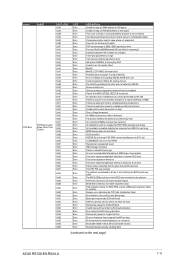
Model Name RS720-E9-RS24-U Motherboard Z11PP-D24 Processor Support 2 x Socket P0 (LGA 3647) 1st Gen Intel®...Channel) Intel® Optane™ DC persistent memory (DCPMM) * 2933MHz will drop to 2666MHz when using 2DPC configurations ** Refer to ASUS server AVL for the latest update Memory Size 4GB, 8GB, 12GB, 32GB, 64GB (RDIMM) 64GB, 128GB, 256GB (RDIMM 3DS) ...® VROC (for Windows and Linux; Support software RAID 0, 1, 10 & 5) (continued on the next page) ASUS RS720-E9-RS24-U 1-3 1.3 System specifications The ASUS RS720-E9-RS24-U features the ASUS Z11PP-D24 server board.
Model Name RS720-E9-RS24-U Motherboard Z11PP-D24 Processor Support 2 x Socket P0 (LGA 3647) 1st Gen Intel®...Channel) Intel® Optane™ DC persistent memory (DCPMM) * 2933MHz will drop to 2666MHz when using 2DPC configurations ** Refer to ASUS server AVL for the latest update Memory Size 4GB, 8GB, 12GB, 32GB, 64GB (RDIMM) 64GB, 128GB, 256GB (RDIMM 3DS) ...® VROC (for Windows and Linux; Support software RAID 0, 1, 10 & 5) (continued on the next page) ASUS RS720-E9-RS24-U 1-3 1.3 System specifications The ASUS RS720-E9-RS24-U features the ASUS Z11PP-D24 server board.

User Manual
Page 15
ASUS RS720-E9-RS24-U 1-5 Model Name Management Solution Out of Band Remote Hardware Software RS720-E9-RS24-U On-Board ASMB9-iKVM for KVM-over-IP ASUS Control Center (Classic) OS Support Please find the latest OS support from http://www.asus.com/ Dimension (Depth x Width x Height) Power Supply (different configuration by region) Environment 750 mm x 444 mm x 88 mm (2U...
ASUS RS720-E9-RS24-U 1-5 Model Name Management Solution Out of Band Remote Hardware Software RS720-E9-RS24-U On-Board ASMB9-iKVM for KVM-over-IP ASUS Control Center (Classic) OS Support Please find the latest OS support from http://www.asus.com/ Dimension (Depth x Width x Height) Power Supply (different configuration by region) Environment 750 mm x 444 mm x 88 mm (2U...

User Manual
Page 17
... HS_CON1 HS_CON2 HS_CON1 HS_CON2 PWR2 The barebone server does not include a floppy disk drive. WARNING HAZARDOUS MOVING PARTS KEEP FINGERS AND OTHER BODY PARTS AWAY ASUS RS720-E9-RS24-U 1-7 SATA/SAS/NVMe backplane 5. 24 x 2.5" storage device trays 6. Front panel (hidden) 7. Asset tag (hidden) 8. A protection film is pre-attached to...the system for proper heat dissipation. SAS expander 9. Redundant Power supply 2. Please remove the protection film before shipping. System fans 4. ASUS Z11PP-D24 Server Board 3. Connect a USB floppy disk drive to use a floppy disk.
... HS_CON1 HS_CON2 HS_CON1 HS_CON2 PWR2 The barebone server does not include a floppy disk drive. WARNING HAZARDOUS MOVING PARTS KEEP FINGERS AND OTHER BODY PARTS AWAY ASUS RS720-E9-RS24-U 1-7 SATA/SAS/NVMe backplane 5. 24 x 2.5" storage device trays 6. Front panel (hidden) 7. Asset tag (hidden) 8. A protection film is pre-attached to...the system for proper heat dissipation. SAS expander 9. Redundant Power supply 2. Please remove the protection film before shipping. System fans 4. ASUS Z11PP-D24 Server Board 3. Connect a USB floppy disk drive to use a floppy disk.

User Manual
Page 19
... Status Description OFF No link GREEN Linked BLINKING Data activity SPEED LED Status Description OFF 10 Mbps connection ORANGE 100 Mbps connection GREEN 1 Gbps connection ASUS RS720-E9-RS24-U 1-9
... Status Description OFF No link GREEN Linked BLINKING Data activity SPEED LED Status Description OFF 10 Mbps connection ORANGE 100 Mbps connection GREEN 1 Gbps connection ASUS RS720-E9-RS24-U 1-9
User Manual
Page 21
... APOB SVC call Correct fuse bits for DIAG_BL loading not set The UmcProgramKeys() function was made An error/data corruption detected on the next page) ASUS RS720-E9-RS24-U 1-11 HVB validation failure for sent msg MCM Steady-state unit test failed S3 Enter failed AGESA BL did not set PSP SMU reserved addresses...
... APOB SVC call Correct fuse bits for DIAG_BL loading not set The UmcProgramKeys() function was made An error/data corruption detected on the next page) ASUS RS720-E9-RS24-U 1-11 HVB validation failure for sent msg MCM Steady-state unit test failed S3 Enter failed AGESA BL did not set PSP SMU reserved addresses...

User Manual
Page 23
... BIOS Setup Utility password verify BIOS Setup Utility start BIOS Setup Utility input wait Ready to boot event Legacy boot event APIC mode PIC mode ASUS RS720-E9-RS24-U 1-13
... BIOS Setup Utility password verify BIOS Setup Utility start BIOS Setup Utility input wait Ready to boot event Legacy boot event APIC mode PIC mode ASUS RS720-E9-RS24-U 1-13

User Manual
Page 27
...the cap on the LGA 3647 socket. • The product warranty does not cover damage to the PnP cap/socket contacts/motherboard components. ASUS will shoulder the cost of repair only if the damage is on the LGA 3647 socket. Remove the air ducts (A), then remove the... and heatsink To install a CPU: 1. Remove the rear cover. Keep the PnP cap. ASUS RS720-E9-RS24-U 2-3 Contact your retailer immediately if the PnP cap is missing, or if you see the section Chassis cover. 2. ASUS will process Return Merchandise Authorization (RMA) requests only if the motherboard comes with the PnP cap...
...the cap on the LGA 3647 socket. • The product warranty does not cover damage to the PnP cap/socket contacts/motherboard components. ASUS will shoulder the cost of repair only if the damage is on the LGA 3647 socket. Remove the air ducts (A), then remove the... and heatsink To install a CPU: 1. Remove the rear cover. Keep the PnP cap. ASUS RS720-E9-RS24-U 2-3 Contact your retailer immediately if the PnP cap is missing, or if you see the section Chassis cover. 2. ASUS will process Return Merchandise Authorization (RMA) requests only if the motherboard comes with the PnP cap...

User Manual
Page 29
6. ASUS RS720-E9-RS24-U 2-5 Reinstall the air ducts to complete.
6. ASUS RS720-E9-RS24-U 2-5 Reinstall the air ducts to complete.

User Manual
Page 31
... modules from the same vendor. and 128GB, 256GB, and 512GB DCPMMs into the DIMM sockets using the memory configurations in this section. • Refer to ASUS Server AVL for 1 CPU Configuration 1 CPU Configuration (must be on CPU1) DIMM_A2 DIMM_A1 DIMM_B2 DIMM_B1 DIMM_C2 DIMM_C1 1 DIMM • 2 DIMMs • 4 DIMMs • • 6 DIMMs... DIMM_F2 DIMM_F1 1 DIMM 2 DIMMs • 4 DIMMs • • 6 DIMMs • • • 8 DIMMs • • • • 12 DIMMs • • • • • • ASUS RS720-E9-RS24-U 2-7
... modules from the same vendor. and 128GB, 256GB, and 512GB DCPMMs into the DIMM sockets using the memory configurations in this section. • Refer to ASUS Server AVL for 1 CPU Configuration 1 CPU Configuration (must be on CPU1) DIMM_A2 DIMM_A1 DIMM_B2 DIMM_B1 DIMM_C2 DIMM_C1 1 DIMM • 2 DIMMs • 4 DIMMs • • 6 DIMMs... DIMM_F2 DIMM_F1 1 DIMM 2 DIMMs • 4 DIMMs • • 6 DIMMs • • • 8 DIMMs • • • • 12 DIMMs • • • • • • ASUS RS720-E9-RS24-U 2-7

User Manual
Page 33
... DCPMM DRAM 1 DRAM1 AD+MM DCPMM DRAM 3 DRAM3 AD DCPMM DRAM 1 DRAM 1 DRAM 1 DRAM1 AD - APP DIRECT MODE MM - RDIMM only DRAM3 - DC PERSISTENT MEMORY ASUS RS720-E9-RS24-U 2-9 MEMORY MODE AD+MM - RDIMM, RDIMM 3DS, LRDIMM DCPMM - MIXED MODE DRAM1 -
... DCPMM DRAM 1 DRAM1 AD+MM DCPMM DRAM 3 DRAM3 AD DCPMM DRAM 1 DRAM 1 DRAM 1 DRAM1 AD - APP DIRECT MODE MM - RDIMM only DRAM3 - DC PERSISTENT MEMORY ASUS RS720-E9-RS24-U 2-9 MEMORY MODE AD+MM - RDIMM, RDIMM 3DS, LRDIMM DCPMM - MIXED MODE DRAM1 -

User Manual
Page 39
... drive tray to the front panel: 1. Switch the secure lock upward to prevent the drive tray from benting or deforming. Pull the tray lever outward. ASUS RS720-E9-RS24-U 2-15 The drive tray ejects slightly after you pull out the lever. Metal beam The metal beam supports the drive tray horizontally to release the...
... drive tray to the front panel: 1. Switch the secure lock upward to prevent the drive tray from benting or deforming. Pull the tray lever outward. ASUS RS720-E9-RS24-U 2-15 The drive tray ejects slightly after you pull out the lever. Metal beam The metal beam supports the drive tray horizontally to release the...

User Manual
Page 41
PCIe slot Slot 4 Slot 5 Operation mode x8 x16 x8 N/A ASUS RS720-E9-RS24-U 2-17 2.5 Expansion slot The barebone server comes with four pre-installed riser cards. Slot 2 can be disabled. Riser card 3 Riser card 2 Riser card 1 Riser card 4 ... auto-switch to bottom. Slot 4 can be disabled. PCIe slot Slot 1 Slot 2 Slot 3 Operation mode x8 N/A x8 x8 (ASUS PIKE II card by default) x16 (ASUS PCIE-NVME4-OCuLink card by default) x8 (ASUS PIKE II card by default) Riser card bracket 2 Riser card bracket 2 supports PCIe Gen3 slots 4-5 top to x16 mode...
PCIe slot Slot 4 Slot 5 Operation mode x8 x16 x8 N/A ASUS RS720-E9-RS24-U 2-17 2.5 Expansion slot The barebone server comes with four pre-installed riser cards. Slot 2 can be disabled. Riser card 3 Riser card 2 Riser card 1 Riser card 4 ... auto-switch to bottom. Slot 4 can be disabled. PCIe slot Slot 1 Slot 2 Slot 3 Operation mode x8 N/A x8 x8 (ASUS PIKE II card by default) x16 (ASUS PCIE-NVME4-OCuLink card by default) x8 (ASUS PIKE II card by default) Riser card bracket 2 Riser card bracket 2 supports PCIe Gen3 slots 4-5 top to x16 mode...

User Manual
Page 43
Riser card bracket 1 ASUS RS720-E9-RS24-U 2-19 Firmly hold riser card bracket 1, then pull it from the PCIE1 slot on the PCIE1 slot supports Full-Height (FH) and HalfLength (HL) PCIE x16 expansion cards. 2.5.1 Installing an expansion card to detach it up to riser card bracket 1 The pre-installed riser card bracket 1 on the motherboard. To install an expansion card to the chassis. 2. Remove the screw that secures riser card bracket 1 to riser card bracket 1: 1.
Riser card bracket 1 ASUS RS720-E9-RS24-U 2-19 Firmly hold riser card bracket 1, then pull it from the PCIE1 slot on the PCIE1 slot supports Full-Height (FH) and HalfLength (HL) PCIE x16 expansion cards. 2.5.1 Installing an expansion card to detach it up to riser card bracket 1 The pre-installed riser card bracket 1 on the motherboard. To install an expansion card to the chassis. 2. Remove the screw that secures riser card bracket 1 to riser card bracket 1: 1.

User Manual
Page 45
Firmly hold riser card bracket 2, then pull it up to detach it from riser card bracket 2. 2.5.2 Installing an expansion card to riser card bracket 2 To install an expansion card on the motherboard. Remove the two screws that secures riser card bracket 2 to the chassis. 2. Riser card bracket 2 4. Remove the screw from the metal cover (A), then remove the metal cover (B) from the PCIE3 slot on riser card bracket 2: 1. Metal cover ASUS RS720-E9-RS24-U 2-21 Remove the screw that secure riser card bracket 2 to the motherboard. 3.
Firmly hold riser card bracket 2, then pull it up to detach it from riser card bracket 2. 2.5.2 Installing an expansion card to riser card bracket 2 To install an expansion card on the motherboard. Remove the two screws that secures riser card bracket 2 to the chassis. 2. Riser card bracket 2 4. Remove the screw from the metal cover (A), then remove the metal cover (B) from the PCIE3 slot on riser card bracket 2: 1. Metal cover ASUS RS720-E9-RS24-U 2-21 Remove the screw that secure riser card bracket 2 to the motherboard. 3.

User Manual
Page 47
Firmly hold riser card bracket 3, then pull it from riser card bracket 3. Remove the screw from the metal cover (A), then remove the metal cover (B) from the PCIE4 slot on riser card bracket 3: 1. Metal cover ASUS RS720-E9-RS24-U 2-23 Riser card bracket 3 3. Remove the two screws that secure riser card bracket 3 to detach it up to the chassis. 2. 2.5.3 Installing an expansion card to riser card bracket 3 To install an expansion card on the motherboard.
Firmly hold riser card bracket 3, then pull it from riser card bracket 3. Remove the screw from the metal cover (A), then remove the metal cover (B) from the PCIE4 slot on riser card bracket 3: 1. Metal cover ASUS RS720-E9-RS24-U 2-23 Riser card bracket 3 3. Remove the two screws that secure riser card bracket 3 to detach it up to the chassis. 2. 2.5.3 Installing an expansion card to riser card bracket 3 To install an expansion card on the motherboard.

User Manual
Page 49
Remove the metal cover from the chassis. Remove the screw that secures the metal lock to riser card bracket 2. 2. Metal cover ASUS RS720-E9-RS24-U 2-25 For more information, refer to section 2.5.1 Installing an expansion card to riser card bracket 1 and 2.5.2 Installing an expansion card to the chassis. 3. Lift the metal lock upward. 2.5.4 Installing an expansion card to riser card bracket 4 To install an expansion card to riser card bracket 4: 1. Remove riser card bracket 1 and riser card bracket 2. Metal lock 4.
Remove the metal cover from the chassis. Remove the screw that secures the metal lock to riser card bracket 2. 2. Metal cover ASUS RS720-E9-RS24-U 2-25 For more information, refer to section 2.5.1 Installing an expansion card to riser card bracket 1 and 2.5.2 Installing an expansion card to the chassis. 3. Lift the metal lock upward. 2.5.4 Installing an expansion card to riser card bracket 4 To install an expansion card to riser card bracket 4: 1. Remove riser card bracket 1 and riser card bracket 2. Metal lock 4.
User Manual
Page 51
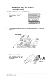
Remove the screw from the metal cover (A), then remove the ASUS PIKE II card (B) from the PCIE1 slot on riser card bracket 1: 1. Riser card bracket 1 3. Remove the screw that secures riser card bracket 1 to detach it up to the chassis. 2. ASUS RS720-E9-RS24-U Metal cover 2-27 Firmly hold riser card bracket 1, then pull it from riser card bracket 1. 2.5.5 Replacing the ASUS PIKE II card on riser card bracket 1 To replace the ASUS PIKE II card on the motherboard.
Remove the screw from the metal cover (A), then remove the ASUS PIKE II card (B) from the PCIE1 slot on riser card bracket 1: 1. Riser card bracket 1 3. Remove the screw that secures riser card bracket 1 to detach it up to the chassis. 2. ASUS RS720-E9-RS24-U Metal cover 2-27 Firmly hold riser card bracket 1, then pull it from riser card bracket 1. 2.5.5 Replacing the ASUS PIKE II card on riser card bracket 1 To replace the ASUS PIKE II card on the motherboard.

User Manual
Page 53
Ensure that the golden connectors of riser card bracket 1 is firmly seated in step 1. Secure riser card bracket 1 to the chassis with the screw removed in place. 9. ASUS RS720-E9-RS24-U 2-29 8. Install the riser card bracket 1 and ASUS PIKE II card assembly into the PCIE1 slot on the motherboard.
Ensure that the golden connectors of riser card bracket 1 is firmly seated in step 1. Secure riser card bracket 1 to the chassis with the screw removed in place. 9. ASUS RS720-E9-RS24-U 2-29 8. Install the riser card bracket 1 and ASUS PIKE II card assembly into the PCIE1 slot on the motherboard.

User Manual
Page 55
OCuLink port 3 OCuLink port 4 OCuLink port 1 OCuLink port 2 7. 4. Prepare the replacement ASUS PCIE-NVME4-OCuLink card. 6. Metal cover ASUS RS720-E9-RS24-U 2-31 Reconnect the default cables to the replacement ASUS PCIE-NVME4-OCuLink card. Install the replacement ASUS PCIE-NVME4-OCuLink card into riser card bracket 1 (A), then secure it with the screw (B). Remove the OCuLink cables. OCuLink port 3 OCuLink port 4 OCuLink port 1 OCuLink port 2 5.
OCuLink port 3 OCuLink port 4 OCuLink port 1 OCuLink port 2 7. 4. Prepare the replacement ASUS PCIE-NVME4-OCuLink card. 6. Metal cover ASUS RS720-E9-RS24-U 2-31 Reconnect the default cables to the replacement ASUS PCIE-NVME4-OCuLink card. Install the replacement ASUS PCIE-NVME4-OCuLink card into riser card bracket 1 (A), then secure it with the screw (B). Remove the OCuLink cables. OCuLink port 3 OCuLink port 4 OCuLink port 1 OCuLink port 2 5.

User Manual
Page 57
Remove the screw that secures the metal lock to riser card bracket 2. 2. ASUS RS720-E9-RS24-U 2-33 For more information, refer to section 2.5.1 Installing an expansion card to riser card bracket 1 and 2.5.2 Installing an expansion card to the chassis. 3. Metal lock 4. 2.5.7 Replacing the ASUS PCIE-NVME4-OCuLink card on riser card bracket 4 To replace the ASUS PCIE-NVME4-OCuLink card on riser card bracket 4: 1. Remove riser card bracket 1 and riser card bracket 2. Lift the metal lock upward. Remove the ASUS PCIE-NVME4-OCuLink card from the chassis.
Remove the screw that secures the metal lock to riser card bracket 2. 2. ASUS RS720-E9-RS24-U 2-33 For more information, refer to section 2.5.1 Installing an expansion card to riser card bracket 1 and 2.5.2 Installing an expansion card to the chassis. 3. Metal lock 4. 2.5.7 Replacing the ASUS PCIE-NVME4-OCuLink card on riser card bracket 4 To replace the ASUS PCIE-NVME4-OCuLink card on riser card bracket 4: 1. Remove riser card bracket 1 and riser card bracket 2. Lift the metal lock upward. Remove the ASUS PCIE-NVME4-OCuLink card from the chassis.


