
STRIX Z270I GAMING Users ManualEnglish
Page 17
... F_PANEL) 12. TPM connector (14-1 pin TPM) 17. M.2 sockets (M.2_2) Page 1-12 1-15 1-16 1-13 1-4 1-14 1-5 1-10 1-10 1-9 1-17 1-16 1-11 1-12 1-8 1-13 1-11 1-8 1-14 ASUS STRIX Z270I GAMING 1-3 LGA1151 CPU socket 6. USB 3.0 connector (20-1 pin USB3_12) 15. RTC Battery header (2-pin BATT_CON) 19. Chapter 1 • M.2_2 is located on the bottom of the motherboard...
... F_PANEL) 12. TPM connector (14-1 pin TPM) 17. M.2 sockets (M.2_2) Page 1-12 1-15 1-16 1-13 1-4 1-14 1-5 1-10 1-10 1-9 1-17 1-16 1-11 1-12 1-8 1-13 1-11 1-8 1-14 ASUS STRIX Z270I GAMING 1-3 LGA1151 CPU socket 6. USB 3.0 connector (20-1 pin USB3_12) 15. RTC Battery header (2-pin BATT_CON) 19. Chapter 1 • M.2_2 is located on the bottom of the motherboard...

STRIX Z270I GAMING Users ManualEnglish
Page 18
ASUS will shoulder the cost of the motherboard, ensure that the PnP cap is on the LGA1151 socket. • The product warranty does not cover damage to the PnP cap/socket contacts/motherboard components. STRIX Z270I GAMING CPU socket LGA1151 • Ensure that all power cables are ...removal, or misplacement/loss/incorrect removal of the PnP cap. 1-4 Chapter 1: Product Introduction ASUS will process Return Merchandise Authorization (RMA) requests only if the motherboard comes with a surface mount LGA1151 socket designed for the 7th / 6th Generation Intel® Core™ i7 / ...
ASUS will shoulder the cost of the motherboard, ensure that the PnP cap is on the LGA1151 socket. • The product warranty does not cover damage to the PnP cap/socket contacts/motherboard components. STRIX Z270I GAMING CPU socket LGA1151 • Ensure that all power cables are ...removal, or misplacement/loss/incorrect removal of the PnP cap. 1-4 Chapter 1: Product Introduction ASUS will process Return Merchandise Authorization (RMA) requests only if the motherboard comes with a surface mount LGA1151 socket designed for the 7th / 6th Generation Intel® Core™ i7 / ...
STRIX Z270I GAMING Users ManualEnglish
Page 21
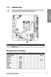
shared - - - shared - shared - shared - shared - shared - shared - ASUS STRIX Z270I GAMING 1-7 Failure to do so may cause you physical injury and damage motherboard components. C D - shared - - - - - Chapter 1 1.1.5 Expansion slots ...SATA6G_2 SATA6G_1 SPEAKER F_PANEL RGB_HEADER DDR4 DIMM_B1 (64bit, 288-pin module) DDR4 DIMM_A1 (64bit, 288-pin module) USB3_34 SATA6G_4 SATA6G_3 HDMI DP LGA1151 LAN_USB3_34 Intel® (Bottom) I219V M.2(WIFI) AIO_PUMP BATT_CON Super I/O T_SENSOR AUDIO AAFP 2280 TPU TPM 2260 128Mb BIOS Intel® ...
shared - - - shared - shared - shared - shared - shared - shared - ASUS STRIX Z270I GAMING 1-7 Failure to do so may cause you physical injury and damage motherboard components. C D - shared - - - - - Chapter 1 1.1.5 Expansion slots ...SATA6G_2 SATA6G_1 SPEAKER F_PANEL RGB_HEADER DDR4 DIMM_B1 (64bit, 288-pin module) DDR4 DIMM_A1 (64bit, 288-pin module) USB3_34 SATA6G_4 SATA6G_3 HDMI DP LGA1151 LAN_USB3_34 Intel® (Bottom) I219V M.2(WIFI) AIO_PUMP BATT_CON Super I/O T_SENSOR AUDIO AAFP 2280 TPU TPM 2260 128Mb BIOS Intel® ...

STRIX Z270I GAMING Users ManualEnglish
Page 35
Chapter 2 Top of CPU Bottom of CPU Bottom of CPU ASUS STRIX Z270I GAMING 2-3 2.1.2 CPU installation Ensure that you install the correct CPU designed for LGA1155 and LGA1156 sockets on the LGA1151 socket. DO NOT install a CPU designed for LGA1151 socket only.
Chapter 2 Top of CPU Bottom of CPU Bottom of CPU ASUS STRIX Z270I GAMING 2-3 2.1.2 CPU installation Ensure that you install the correct CPU designed for LGA1155 and LGA1156 sockets on the LGA1151 socket. DO NOT install a CPU designed for LGA1151 socket only.

STRIX Z270I GAMING Users ManualEnglish
Page 36
... Tool. • Always firmly hold both sides of CPU Chapter 2 • The CPU Installation Tool is only compatible on ASUS motherboards with a Intel® LGA1151 socket. • Ensure that the CPU is firmly clicked into place before installing it onto the CPU socket on the motherboard..... • Ensure to use a soft stable surface when installing the CPU to the CPU Installation Tool to prevent CPU damage. • ASUS will not cover damages resulting from incorrect CPU installation/removal, incorrect CPU orientation/placement, or other damages resulting from negligence by the user. 2-4...
... Tool. • Always firmly hold both sides of CPU Chapter 2 • The CPU Installation Tool is only compatible on ASUS motherboards with a Intel® LGA1151 socket. • Ensure that the CPU is firmly clicked into place before installing it onto the CPU socket on the motherboard..... • Ensure to use a soft stable surface when installing the CPU to the CPU Installation Tool to prevent CPU damage. • ASUS will not cover damages resulting from incorrect CPU installation/removal, incorrect CPU orientation/placement, or other damages resulting from negligence by the user. 2-4...

STRIX Z270I GAMING USER S MANUAL ENGLISH
Page 16
... DRAM_LED CPU_LED RGBLED EATXPWR SATA6G_2 SATA6G_1 SPEAKER F_PANEL RGB_HEADER DDR4 DIMM_B1 (64bit, 288-pin module) DDR4 DIMM_A1 (64bit, 288-pin module) 2 18 17 HDMI DP LGA1151 LAN_USB3_34 Intel® (Bottom) I219V M.2(WIFI) AIO_PUMP BATT_CON Super I/O T_SENSOR AUDIO AAFP 2280 TPU TPM 2260 128Mb BIOS Intel® Z270 ALC 1220 CHA_FAN PCIEX16_1...
... DRAM_LED CPU_LED RGBLED EATXPWR SATA6G_2 SATA6G_1 SPEAKER F_PANEL RGB_HEADER DDR4 DIMM_B1 (64bit, 288-pin module) DDR4 DIMM_A1 (64bit, 288-pin module) 2 18 17 HDMI DP LGA1151 LAN_USB3_34 Intel® (Bottom) I219V M.2(WIFI) AIO_PUMP BATT_CON Super I/O T_SENSOR AUDIO AAFP 2280 TPU TPM 2260 128Mb BIOS Intel® Z270 ALC 1220 CHA_FAN PCIEX16_1...

STRIX Z270I GAMING USER S MANUAL ENGLISH
Page 17
... 4-pin AIO_PUMP, 4-pin CHA_FAN) 3. RGB LED 10, RGB header (4-pin RGB_HEADER) 11. USB 3.1 front panel connector (USB3.1_EC1) 2. LGA1151 CPU socket 6. POST State LEDs 9. System panel connector (10-1 pin F_PANEL) 12. Speaker connector (4-pin SPEAKER) 13. USB 3.0 connector (...header (2-pin BATT_CON) Page 1-14 1-16 1-17 1-15 1-4 1-15 1-5 1-11 1-11 1-10 1-18 1-17 1-13 1-13 1-9 1-14 1-12 1-9 ASUS STRIX Z270I GAMING 1-3 Thermal sensor cable connector (2-pin T_SENSOR) 5. Clear RTC RAM (2-pin CLRTC) 16. Chapter 1 Layout contents Connectors/Jumpers/Buttons and switches/Slots 1. M.2 sockets ...
... 4-pin AIO_PUMP, 4-pin CHA_FAN) 3. RGB LED 10, RGB header (4-pin RGB_HEADER) 11. USB 3.1 front panel connector (USB3.1_EC1) 2. LGA1151 CPU socket 6. POST State LEDs 9. System panel connector (10-1 pin F_PANEL) 12. Speaker connector (4-pin SPEAKER) 13. USB 3.0 connector (...header (2-pin BATT_CON) Page 1-14 1-16 1-17 1-15 1-4 1-15 1-5 1-11 1-11 1-10 1-18 1-17 1-13 1-13 1-9 1-14 1-12 1-9 ASUS STRIX Z270I GAMING 1-3 Thermal sensor cable connector (2-pin T_SENSOR) 5. Clear RTC RAM (2-pin CLRTC) 16. Chapter 1 Layout contents Connectors/Jumpers/Buttons and switches/Slots 1. M.2 sockets ...

STRIX Z270I GAMING USER S MANUAL ENGLISH
Page 18
...cap is shipment/ transit-related. • Keep the cap after installing the motherboard. ASUS will process Return Merchandise Authorization (RMA) requests only if the motherboard comes with a surface mount LGA1151 socket designed for the 7th / 6th Generation Intel® Core™ i7 / Intel...1 1.1.3 Central Processing Unit (CPU) The motherboard comes with the cap on the socket and the socket contacts are not bent. STRIX Z270I GAMING CPU socket LGA1151 • Ensure that all power cables are unplugged before installing the CPU. • Upon purchase of the PnP cap. 1-4 Chapter ...
...cap is shipment/ transit-related. • Keep the cap after installing the motherboard. ASUS will process Return Merchandise Authorization (RMA) requests only if the motherboard comes with a surface mount LGA1151 socket designed for the 7th / 6th Generation Intel® Core™ i7 / Intel...1 1.1.3 Central Processing Unit (CPU) The motherboard comes with the cap on the socket and the socket contacts are not bent. STRIX Z270I GAMING CPU socket LGA1151 • Ensure that all power cables are unplugged before installing the CPU. • Upon purchase of the PnP cap. 1-4 Chapter ...

STRIX Z270I GAMING USER S MANUAL ENGLISH
Page 21
... (64bit, 288-pin module) USB3_34 SATA6G_4 SATA6G_3 HDMI DP LGA1151 LAN_USB3_34 Intel® (Bottom) I219V M.2(WIFI) AIO_PUMP BATT_CON Super I/O T_SENSOR AUDIO AAFP 2280 TPU TPM 2260 128Mb BIOS Intel® Z270 ALC CHA_FAN 1220 PCIEX16_1 1 M.2_1(SOCKET3) M.2_2(SOCKET3)Bottom CLRTC PCIE SATA IRST X4 V V Slot No. Slot Description 1 PCIEx16_1 slot ASUS STRIX Z270I GAMING 1-7
... (64bit, 288-pin module) USB3_34 SATA6G_4 SATA6G_3 HDMI DP LGA1151 LAN_USB3_34 Intel® (Bottom) I219V M.2(WIFI) AIO_PUMP BATT_CON Super I/O T_SENSOR AUDIO AAFP 2280 TPU TPM 2260 128Mb BIOS Intel® Z270 ALC CHA_FAN 1220 PCIEX16_1 1 M.2_1(SOCKET3) M.2_2(SOCKET3)Bottom CLRTC PCIE SATA IRST X4 V V Slot No. Slot Description 1 PCIEx16_1 slot ASUS STRIX Z270I GAMING 1-7

STRIX Z270I GAMING USER S MANUAL ENGLISH
Page 35
DO NOT install a CPU designed for LGA1151 socket only. 2.1.2 CPU installation Ensure that you install the correct CPU designed for LGA1155 and LGA1156 sockets on the LGA1151 socket. Chapter 2 Top of CPU Bottom of CPU Bottom of CPU ASUS STRIX Z270I GAMING 2-3
DO NOT install a CPU designed for LGA1151 socket only. 2.1.2 CPU installation Ensure that you install the correct CPU designed for LGA1155 and LGA1156 sockets on the LGA1151 socket. Chapter 2 Top of CPU Bottom of CPU Bottom of CPU ASUS STRIX Z270I GAMING 2-3

STRIX Z270I GAMING USER S MANUAL ENGLISH
Page 36
... Tool. • Always firmly hold both sides of CPU Chapter 2 • The CPU Installation Tool is only compatible on ASUS motherboards with a Intel® LGA1151 socket. • Ensure that the CPU is firmly clicked into place before installing it onto the CPU socket on the motherboard..... • Ensure to use a soft stable surface when installing the CPU to the CPU Installation Tool to prevent CPU damage. • ASUS will not cover damages resulting from incorrect CPU installation/removal, incorrect CPU orientation/placement, or other damages resulting from negligence by the user. 2-4...
... Tool. • Always firmly hold both sides of CPU Chapter 2 • The CPU Installation Tool is only compatible on ASUS motherboards with a Intel® LGA1151 socket. • Ensure that the CPU is firmly clicked into place before installing it onto the CPU socket on the motherboard..... • Ensure to use a soft stable surface when installing the CPU to the CPU Installation Tool to prevent CPU damage. • ASUS will not cover damages resulting from incorrect CPU installation/removal, incorrect CPU orientation/placement, or other damages resulting from negligence by the user. 2-4...