User Manual
Page 11
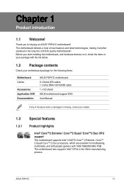
...supports Intel® LGA775 Core™ 2 Extreme / Core™ 2 Quad/ Core™ 2 Duo processors, which are excellent for buying an ASUS® P5P41C motherboard! Thank you start installing the motherboard, and hardware devices on it another standout in the 45nm manufacturing process. Before you for multitasking, multimedia,... with the list below. 1.2 Package contents Check your motherboard package for the following items. Motherboard Cables Accessories Application DVD Documentation ASUS P5P41C motherboard 2 x Serial ATA cables 1 x Ultra DMA 133/100/66 cable 1 x I/O shield...
...supports Intel® LGA775 Core™ 2 Extreme / Core™ 2 Quad/ Core™ 2 Duo processors, which are excellent for buying an ASUS® P5P41C motherboard! Thank you start installing the motherboard, and hardware devices on it another standout in the 45nm manufacturing process. Before you for multitasking, multimedia,... with the list below. 1.2 Package contents Check your motherboard package for the following items. Motherboard Cables Accessories Application DVD Documentation ASUS P5P41C motherboard 2 x Serial ATA cables 1 x Ultra DMA 133/100/66 cable 1 x I/O shield...
User Manual
Page 13
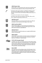
C.P.R. (CPU Parameter Recall) The BIOS C.P.R. ASUS P5P41C 1-3 When installing it on USB HDDs or flash drives, connect the drives to the motherboard USB port before entering the Windows® OS. • ASUS Express Gate supports installation on SATA HDDs, USB HDDs and flash drives with at 1 meter accuracy.... the impact on your favorite photo into a 256-color boot logo for a more colorful and vivid image on the environment. ASUS CrashFree BIOS 3 ASUS CrashFree BIOS 3 is an auto-recovery tool that allows you to convert your screen. Simply shut down and reboot the system,...
C.P.R. (CPU Parameter Recall) The BIOS C.P.R. ASUS P5P41C 1-3 When installing it on USB HDDs or flash drives, connect the drives to the motherboard USB port before entering the Windows® OS. • ASUS Express Gate supports installation on SATA HDDs, USB HDDs and flash drives with at 1 meter accuracy.... the impact on your favorite photo into a 256-color boot logo for a more colorful and vivid image on the environment. ASUS CrashFree BIOS 3 ASUS CrashFree BIOS 3 is an auto-recovery tool that allows you to convert your screen. Simply shut down and reboot the system,...

User Manual
Page 15
.... 1.5.1 Placement direction When installing the motherboard, ensure that you place it . Do not overtighten the screws! Place this side towards the rear of the chassis P5P41C ASUS P5P41C 1-5 Failure to do so can damage the motherboard. The edge with external ports goes to the rear part of the chassis as indicated in the...
.... 1.5.1 Placement direction When installing the motherboard, ensure that you place it . Do not overtighten the screws! Place this side towards the rear of the chassis P5P41C ASUS P5P41C 1-5 Failure to do so can damage the motherboard. The edge with external ports goes to the rear part of the chassis as indicated in the...

User Manual
Page 17
... the cost of repair only if the damage is on the socket and the socket contacts are not bent. ASUS P5P41C 1-7 The motherboard supports Intel® LGA775 processors with the Intel® Enhanced Intel SpeedStep® Technology (EIST) and Hyper-Threading Technology.... product warranty does not cover damage to the PnP cap/socket contacts/motherboard components. ASUS will process Return Merchandise Authorization (RMA) requests only if the motherboard comes with the cap on the motherboard. P5P41C P5P41C CPU socket 775 Before installing the CPU, ensure that the PnP cap is missing,...
... the cost of repair only if the damage is on the socket and the socket contacts are not bent. ASUS P5P41C 1-7 The motherboard supports Intel® LGA775 processors with the Intel® Enhanced Intel SpeedStep® Technology (EIST) and Hyper-Threading Technology.... product warranty does not cover damage to the PnP cap/socket contacts/motherboard components. ASUS will process Return Merchandise Authorization (RMA) requests only if the motherboard comes with the cap on the motherboard. P5P41C P5P41C CPU socket 775 Before installing the CPU, ensure that the PnP cap is missing,...

User Manual
Page 19
To prevent contaminating the paste, DO NOT spread the paste with pre-applied thermal paste. If so, skip this step. B ASUS P5P41C 1-9 DO NOT eat the Thermal Interface Material. If it snaps into your eyes or touches your finger directly. 7. Close the load plate (A), then push the ...
To prevent contaminating the paste, DO NOT spread the paste with pre-applied thermal paste. If so, skip this step. B ASUS P5P41C 1-9 DO NOT eat the Thermal Interface Material. If it snaps into your eyes or touches your finger directly. 7. Close the load plate (A), then push the ...
User Manual
Page 21
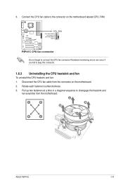
... fan cable to plug this connector. 1.6.3 Uninstalling the CPU heatsink and fan To uninstall the CPU heatsink and fan: 1. A A B B B A B A ASUS P5P41C 1-11 3. P5P41C CPU_FAN CPU FAN PWM CPU FAN IN CPU FAN PWR GND P5P41C CPU fan connector Do not forget to disengage the heatsink and fan assembly from the connector on the motherboard...
... fan cable to plug this connector. 1.6.3 Uninstalling the CPU heatsink and fan To uninstall the CPU heatsink and fan: 1. A A B B B A B A ASUS P5P41C 1-11 3. P5P41C CPU_FAN CPU FAN PWM CPU FAN IN CPU FAN PWR GND P5P41C CPU fan connector Do not forget to disengage the heatsink and fan assembly from the connector on the motherboard...
User Manual
Page 23
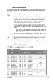
...• • 7 - • • - - • • - - • • - - • • 7-7-7-20 - • • - - • • - - • • ASUS P5P41C 1-13 1.7.2 Memory configurations You may install 512MB, 1GB, 2GB, and 4GB unbuffered non‑ECC DDR3 DIMMS into the black sockets or 512MB, 1GB, 2GB... dependent on the motherboard. • This motherboard does not support DIMMs made up of the following: - P5P41C Motherboard Qualified Vendors Lists (QVL) DDR3-1066 MHz capability Vendor Part No. Install a 64-bit Windows®...
...• • 7 - • • - - • • - - • • - - • • 7-7-7-20 - • • - - • • - - • • ASUS P5P41C 1-13 1.7.2 Memory configurations You may install 512MB, 1GB, 2GB, and 4GB unbuffered non‑ECC DDR3 DIMMS into the black sockets or 512MB, 1GB, 2GB... dependent on the motherboard. • This motherboard does not support DIMMs made up of the following: - P5P41C Motherboard Qualified Vendors Lists (QVL) DDR3-1066 MHz capability Vendor Part No. Install a 64-bit Windows®...

User Manual
Page 25
... A3P1GF3DGF928M9B05 - N2CB1680AN-C6 - 9 - 7-7-7-20 1.5V 8-8-8-24 1.5V 7-7-7-20 1.5V 8-8-8-24 1.5V 8-8-8-24 1.5V • • • • • • • • • • • • ASUS P5P41C 1-15 OCZ OCZ3P13334GK OCZ OCZ3P1333LV4GK OCZ OCZ OCZ OCZ OCZ OCZ PSC PSC SAMSUNG OCZ3P1333LV4GK OCZ3RPX1333EB4GK OCZ3X13334GK(XMP) OCZ3G1333LV6GK OCZ3P1333LV6GK OCZ3X1333LV6GK(XMP) AL7F8G73D-DG1 AL8F8G73D...
... A3P1GF3DGF928M9B05 - N2CB1680AN-C6 - 9 - 7-7-7-20 1.5V 8-8-8-24 1.5V 7-7-7-20 1.5V 8-8-8-24 1.5V 8-8-8-24 1.5V • • • • • • • • • • • • ASUS P5P41C 1-15 OCZ OCZ3P13334GK OCZ OCZ3P1333LV4GK OCZ OCZ OCZ OCZ OCZ OCZ PSC PSC SAMSUNG OCZ3P1333LV4GK OCZ3RPX1333EB4GK OCZ3X13334GK(XMP) OCZ3G1333LV6GK OCZ3P1333LV6GK OCZ3X1333LV6GK(XMP) AL7F8G73D-DG1 AL8F8G73D...

User Manual
Page 27
... 5 - • • Transced TQ243PCF8 5 - • • Elpida E1108ACBG-8E-E 5 - • • V-Data VD29608A8A-25EG20813 - - • • Samsung K4T51083QE - - • • Hynix H5PS1G83EFRS6C 852AK - - • • ASUS P5P41C 1-17 Size SS/ DS GEIL GE24GB800C5QC 1024MB DS GEIL GX22GB6400DC 1024MB DS GEIL GX22GB6400UDC 1024MB DS GEIL GB24GB6400C4DC 2048MB DS GEIL GB24GB6400C5DC 2048MB DS GEIL...
... 5 - • • Transced TQ243PCF8 5 - • • Elpida E1108ACBG-8E-E 5 - • • V-Data VD29608A8A-25EG20813 - - • • Samsung K4T51083QE - - • • Hynix H5PS1G83EFRS6C 852AK - - • • ASUS P5P41C 1-17 Size SS/ DS GEIL GE24GB800C5QC 1024MB DS GEIL GX22GB6400DC 1024MB DS GEIL GX22GB6400UDC 1024MB DS GEIL GB24GB6400C4DC 2048MB DS GEIL GB24GB6400C5DC 2048MB DS GEIL...
User Manual
Page 29
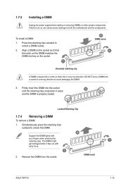
... that the notch on the DIMM matches the DIMM slot key on the socket. 1 2 DIMM notch 1 Unlocked retaining clip A DIMM is properly seated. DIMM notch ASUS P5P41C 1-19
... that the notch on the DIMM matches the DIMM slot key on the socket. 1 2 DIMM notch 1 Unlocked retaining clip A DIMM is properly seated. DIMM notch ASUS P5P41C 1-19
User Manual
Page 31
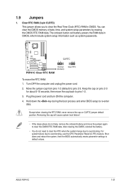
The onboard button cell battery powers the RAM data in CMOS. P5P41C CLRTC 12 23 P5P41C Clear RTC RAM Normal (Default) Clear RTC To erase the RTC RAM: 1. For system failure due to pins 2-3. Shut down the key during the boot ..., remove the onboard battery and move the cap back to re-enter data. Clear RTC RAM (3-pin CLRTC) This jumper allows you to overclocking. 1.9 Jumpers 1. ASUS P5P41C 1-21
The onboard button cell battery powers the RAM data in CMOS. P5P41C CLRTC 12 23 P5P41C Clear RTC RAM Normal (Default) Clear RTC To erase the RTC RAM: 1. For system failure due to pins 2-3. Shut down the key during the boot ..., remove the onboard battery and move the cap back to re-enter data. Clear RTC RAM (3-pin CLRTC) This jumper allows you to overclocking. 1.9 Jumpers 1. ASUS P5P41C 1-21
User Manual
Page 33
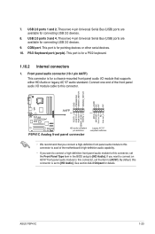
...connect an AC'97 front panel audio module to this connector is for a PS/2 keyboard. 1.10.2 Internal connectors 1. USB 2.0 ports 1 and 2. COM port. ASUS P5P41C 1-23 This port is for connecting USB 2.0 devices. 8. 7. This port is for a chassis-mounted front panel audio I /O module cable to this connector, ... Front Panel Type item in the BIOS setup to [AC97]. USB 2.0 ports 3 and 4. GND PRESENCE# SENSE1_RETUR SENSE2_RETUR AGND NC NC NC P5P41C AAFP PIN 1 PIN 1 MIC2 MICPWR Line out_R NC Line out_L PORT1 L PORT1 R PORT2 R SENSE_SEND PORT2 L HD-audio-compliant pin definition...
...connect an AC'97 front panel audio module to this connector is for a PS/2 keyboard. 1.10.2 Internal connectors 1. USB 2.0 ports 1 and 2. COM port. ASUS P5P41C 1-23 This port is for connecting USB 2.0 devices. 8. 7. This port is for a chassis-mounted front panel audio I /O module cable to this connector, ... Front Panel Type item in the BIOS setup to [AC97]. USB 2.0 ports 3 and 4. GND PRESENCE# SENSE1_RETUR SENSE2_RETUR AGND NC NC NC P5P41C AAFP PIN 1 PIN 1 MIC2 MICPWR Line out_R NC Line out_L PORT1 L PORT1 R PORT2 R SENSE_SEND PORT2 L HD-audio-compliant pin definition...

User Manual
Page 35
... firmly until the connectors completely fit. com/PowerSupplyCalculator/PSCalculator.aspx?SLanguage=en-us for ATX power supply plugs. ATX12V EATXPWR P5P41C +12V DC +12V DC PIN 1 GND +3 Volts GND +12 Volts +12 Volts +5V Standby Power OK GND...+3 Volts PIN 1 GND +5 Volts +5 Volts +5 Volts -5 Volts GND GND GND PSON# GND -12 Volts +3 Volts P5P41C ATX power connectors • We recommend that you intend to connect the 4-pin ATX +12V power plug. The system may become...-pin EATXPWR, 4-pin ATX12V) These connectors are designed to install additional devices. 3. ASUS P5P41C 1-25
... firmly until the connectors completely fit. com/PowerSupplyCalculator/PSCalculator.aspx?SLanguage=en-us for ATX power supply plugs. ATX12V EATXPWR P5P41C +12V DC +12V DC PIN 1 GND +3 Volts GND +12 Volts +12 Volts +5V Standby Power OK GND...+3 Volts PIN 1 GND +5 Volts +5 Volts +5 Volts -5 Volts GND GND GND PSON# GND -12 Volts +3 Volts P5P41C ATX power connectors • We recommend that you intend to connect the 4-pin ATX +12V power plug. The system may become...-pin EATXPWR, 4-pin ATX12V) These connectors are designed to install additional devices. 3. ASUS P5P41C 1-25

User Manual
Page 37
...caps on the motherboard, ensuring that the black wire of each cable matches the ground pin of the system chassis. +5V SPDIFOUT GND P5P41C SPDIF_OUT P5P41C Digital audio connector The S/PDIF module is for an additional Sony/Philips Digital Interface (S/PDIF) port. Do not forget to connect the .... 7. Connect the S/PDIF Out module cable to this connector, then install the module to a slot opening at the back of the connector. ASUS P5P41C 1-27 6. CPU and chassis fan connectors (4-pin CPU_FAN, 3-pin CHA_FAN) Connect the fan cables to the fan connectors. Insufficient air flow inside ...
...caps on the motherboard, ensuring that the black wire of each cable matches the ground pin of the system chassis. +5V SPDIFOUT GND P5P41C SPDIF_OUT P5P41C Digital audio connector The S/PDIF module is for an additional Sony/Philips Digital Interface (S/PDIF) port. Do not forget to connect the .... 7. Connect the S/PDIF Out module cable to this connector, then install the module to a slot opening at the back of the connector. ASUS P5P41C 1-27 6. CPU and chassis fan connectors (4-pin CPU_FAN, 3-pin CHA_FAN) Connect the fan cables to the fan connectors. Insufficient air flow inside ...

User Manual
Page 39
...The Support DVD that comes with the motherboard package contains the drivers, software applications, and utilities that you can install to change at www.asus.com for reference only. The contents of the Support DVD are subject to avail all motherboard features. The following screen is NOT enabled ...click the ASSETUP.EXE to run the Support DVD Place the Support DVD to locate the file ASSETUP.EXE from the BIN folder. ASUS P5P41C 1-29 Visit the ASUS website at any time without notice. Click an icon to display Support DVD/ motherboard information Click an item to maximize the features ...
...The Support DVD that comes with the motherboard package contains the drivers, software applications, and utilities that you can install to change at www.asus.com for reference only. The contents of the Support DVD are subject to avail all motherboard features. The following screen is NOT enabled ...click the ASSETUP.EXE to run the Support DVD Place the Support DVD to locate the file ASSETUP.EXE from the BIN folder. ASUS P5P41C 1-29 Visit the ASUS website at any time without notice. Click an icon to display Support DVD/ motherboard information Click an item to maximize the features ...
User Manual
Page 41
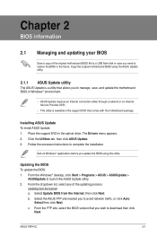
... FTP site, select the BIOS version that comes with the motherboard package. Click the Utilities tab, then click ASUS Update. 3. Copy the original motherboard BIOS using this utility. Select Update BIOS from the Internet a. ASUS P5P41C 2-1 Place the support DVD in the optical drive. Chapter 2 BIOS information 2.1 Managing and updating your BIOS Save...
... FTP site, select the BIOS version that comes with the motherboard package. Click the Utilities tab, then click ASUS Update. 3. Copy the original motherboard BIOS using this utility. Select Update BIOS from the Internet a. ASUS P5P41C 2-1 Place the support DVD in the optical drive. Chapter 2 BIOS information 2.1 Managing and updating your BIOS Save...
User Manual
Page 43
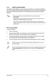
The utility automatically checks the devices for details. ASUS P5P41C 2-3 For motherboards without the floppy connector, prepare a USB flash ...motherboard support DVD or a removable device that allows you to ensure system compatibility and stability. 2.1.3 ASUS CrashFree BIOS The ASUS CrashFree BIOS is an auto recovery tool that contains the updated BIOS file. • Before using ...this utility, rename the BIOS file in the removable device into P5P41C.ROM. • The BIOS...
The utility automatically checks the devices for details. ASUS P5P41C 2-3 For motherboards without the floppy connector, prepare a USB flash ...motherboard support DVD or a removable device that allows you to ensure system compatibility and stability. 2.1.3 ASUS CrashFree BIOS The ASUS CrashFree BIOS is an auto recovery tool that contains the updated BIOS file. • Before using ...this utility, rename the BIOS file in the removable device into P5P41C.ROM. • The BIOS...

User Manual
Page 45
... configuration. Advanced For changing the advanced system settings. Exit For selecting the exit options and loading default settings. Tools For configuring options for special functions. ASUS P5P41C 2-5 Power For changing the advanced power management (APM) configuration. 2.2.1 BIOS menu screen Menu items Menu bar Main Advanced Power Configuration fields BIOS SETUP UTILITY Boot...
... configuration. Advanced For changing the advanced system settings. Exit For selecting the exit options and loading default settings. Tools For configuring options for special functions. ASUS P5P41C 2-5 Power For changing the advanced power management (APM) configuration. 2.2.1 BIOS menu screen Menu items Menu bar Main Advanced Power Configuration fields BIOS SETUP UTILITY Boot...

User Manual
Page 47
... device is installed in the system. Refer to section 2.2.1 BIOS menu screen for each IDE/SATA device. Select a device item then press to select a field. ASUS P5P41C 2-7 Main Advanced BIOS SETUP UTILITY Power Boot Tools Exit System Time System Date Primary IDE Master Primary IDE Slave SATA 1 SATA 2 SATA 3 SATA 4 [12:56...
... device is installed in the system. Refer to section 2.2.1 BIOS menu screen for each IDE/SATA device. Select a device item then press to select a field. ASUS P5P41C 2-7 Main Advanced BIOS SETUP UTILITY Power Boot Tools Exit System Time System Date Primary IDE Master Primary IDE Slave SATA 1 SATA 2 SATA 3 SATA 4 [12:56...
User Manual
Page 49
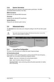
... settings for stability when overclocking. Overclock Profile - 2.3.5 System Information This menu gives you an overview of CPU overclocking options to achieve desired CPU internal frequency. ASUS P5P41C 2-9 The BIOS automatically detects the items in this menu. Take caution when changing the settings of the preset overclocking configuration options: Manual - Select either one...
... settings for stability when overclocking. Overclock Profile - 2.3.5 System Information This menu gives you an overview of CPU overclocking options to achieve desired CPU internal frequency. ASUS P5P41C 2-9 The BIOS automatically detects the items in this menu. Take caution when changing the settings of the preset overclocking configuration options: Manual - Select either one...


