
Motherboard Installation Guide
Page 62
P5ND2-SLI PLED+ PLED+5V Ground Ground Speaker P5ND2-SLI IDE_LED+ IDE_LED- P5ND2-SLI Series System panel connector 2-36 PWR Ground Reset Ground ® P5ND2-SLI Series EZ selector card connector PLED SPEAKER PANEL IDE_LED RESET ® PWR * Requires an ATX power supply.
P5ND2-SLI PLED+ PLED+5V Ground Ground Speaker P5ND2-SLI IDE_LED+ IDE_LED- P5ND2-SLI Series System panel connector 2-36 PWR Ground Reset Ground ® P5ND2-SLI Series EZ selector card connector PLED SPEAKER PANEL IDE_LED RESET ® PWR * Requires an ATX power supply.

P5ND2-SLI Series User''s Manual for English Edition
Page 8
... from the electrical outlet before relocating the system. • When adding or removing devices to or from the system, ensure that your power supply is broken, do not try to the correct voltage in any damage, contact your retailer. If you are not sure about the voltage of the... circuits, keep paper clips, screws, and staples away from the motherboard, ensure that came with the product, contact a qualified service technician or your local power company. • If the power supply is set to fix it , carefully read all the manuals that all cables are correctly connected and the...
... from the electrical outlet before relocating the system. • When adding or removing devices to or from the system, ensure that your power supply is broken, do not try to the correct voltage in any damage, contact your retailer. If you are not sure about the voltage of the... circuits, keep paper clips, screws, and staples away from the motherboard, ensure that came with the product, contact a qualified service technician or your local power company. • If the power supply is set to fix it , carefully read all the manuals that all cables are correctly connected and the...

P5ND2-SLI Series User''s Manual for English Edition
Page 13
P5ND2-SLI Series specifications summary BIOS features Power Requirement Rear panel Internal connectors 4 MB Flash ROM, Phoenix-Award BIOS, PnP, DMI2.0, SM BIOS 2.3, WfM2.0 ATX power supply (with 24-pin and 4-pin 12 V plugs) ATX 12 V 2.0 compliant ASUS EZ Plug* (*When using two graphics cards ... x NVIDIA® nForce™ 4 Serial ATA connectors 1 x Silicon Image SATA connector (Deluxe model only) 1 x Serial port connector (COM port) 1 x 24-pin ATX power connector 1 x 4-pin ATX 12 V power connector 1 x 4-pin ASUS EZ Plug™ connector 3 x USB connectors for 6 additional USB 2.0 ports 1 x ...
P5ND2-SLI Series specifications summary BIOS features Power Requirement Rear panel Internal connectors 4 MB Flash ROM, Phoenix-Award BIOS, PnP, DMI2.0, SM BIOS 2.3, WfM2.0 ATX power supply (with 24-pin and 4-pin 12 V plugs) ATX 12 V 2.0 compliant ASUS EZ Plug* (*When using two graphics cards ... x NVIDIA® nForce™ 4 Serial ATA connectors 1 x Silicon Image SATA connector (Deluxe model only) 1 x Serial port connector (COM port) 1 x 24-pin ATX power connector 1 x 4-pin ATX 12 V power connector 1 x 4-pin ASUS EZ Plug™ connector 3 x USB connectors for 6 additional USB 2.0 ports 1 x ...

P5ND2-SLI Series User''s Manual for English Edition
Page 27
... any component, ensure that the system is ON, in sleep mode, or in the bag that came with a standby power LED. This is switched off or the p o w e r c o r d i s d e t a c h e d f r o m t h e p o w e r s u p p l y . ASUS P5ND2-SLI Series 2-1 The red warning LED lights up to indicate that the ATX power supply is a reminder that you should shut down the system and unplug the...
... any component, ensure that the system is ON, in sleep mode, or in the bag that came with a standby power LED. This is switched off or the p o w e r c o r d i s d e t a c h e d f r o m t h e p o w e r s u p p l y . ASUS P5ND2-SLI Series 2-1 The red warning LED lights up to indicate that the ATX power supply is a reminder that you should shut down the system and unplug the...

P5ND2-SLI Series User''s Manual for English Edition
Page 43
...the socket such that it flips out with your fingers when pressing the retaining clips. Remove the DIMM from the socket. 2 1 DDR2 DIMM notch ASUS P5ND2-SLI Series 2-17 Simultaneously press the retaining clips outward to both the motherboard and the components. To install a DIMM: 1. Do not force a DIMM ...DO not install DDR DIMMs to the DDR2 DIMM sockets. 2.4.4 Removing a DIMM Follow these steps to remove a DIMM. 1. 2.4.3 Installing a DIMM Unplug the power supply before adding or removing DIMMs or other system components. Support the DIMM lightly with extra force. 2.
...the socket such that it flips out with your fingers when pressing the retaining clips. Remove the DIMM from the socket. 2 1 DDR2 DIMM notch ASUS P5ND2-SLI Series 2-17 Simultaneously press the retaining clips outward to both the motherboard and the components. To install a DIMM: 1. Do not force a DIMM ...DO not install DDR DIMMs to the DDR2 DIMM sockets. 2.4.4 Removing a DIMM Follow these steps to remove a DIMM. 1. 2.4.3 Installing a DIMM Unplug the power supply before adding or removing DIMMs or other system components. Support the DIMM lightly with extra force. 2.

P5ND2-SLI Series User''s Manual for English Edition
Page 47
... A N graphics card setup PCIEX16_2 (black) slot Card Type Qualified RAID or LAN card Speed x1 Qualified SLI-ready graphics card Qualified PCIe graphics card, RAID or LAN card x8 x8, x4, x2, x1 ASUS P5ND2-SLI Series 2-21 See page 2-33 for details. • Connect the EZ Plug™ when using two .... The figure shows a graphics card installed on the SLI technology feature. • Install a rear chassis fan to either the chassis (CHA_FAN1) or NorthBridge (NB_FAN) connectors when using two graphics cards and a 20-pin ATX power supply. • In Single Card mode, only the PCI...
... A N graphics card setup PCIEX16_2 (black) slot Card Type Qualified RAID or LAN card Speed x1 Qualified SLI-ready graphics card Qualified PCIe graphics card, RAID or LAN card x8 x8, x4, x2, x1 ASUS P5ND2-SLI Series 2-21 See page 2-33 for details. • Connect the EZ Plug™ when using two .... The figure shows a graphics card installed on the SLI technology feature. • Install a rear chassis fan to either the chassis (CHA_FAN1) or NorthBridge (NB_FAN) connectors when using two graphics cards and a 20-pin ATX power supply. • In Single Card mode, only the PCI...

P5ND2-SLI Series User''s Manual for English Edition
Page 60
... DC +12V DC +12 Volts GND GND +5V Standby Power OK EZ_PLUG Ground +5 Volts Ground +5 Volts ® Ground +3 Volts P5ND2-SLI Series ATX power connectors +3 Volts Ground +5 Volts +5 Volts +5 Volts -5 Volts Ground Ground Ground PSON# Ground -12 Volts +3 Volts 2-34 Chapter 2: Hardware information The power supply plugs are for a chassis-mounted intrusion detection sensor or switch...
... DC +12V DC +12 Volts GND GND +5V Standby Power OK EZ_PLUG Ground +5 Volts Ground +5 Volts ® Ground +3 Volts P5ND2-SLI Series ATX power connectors +3 Volts Ground +5 Volts +5 Volts +5 Volts -5 Volts Ground Ground Ground PSON# Ground -12 Volts +3 Volts 2-34 Chapter 2: Hardware information The power supply plugs are for a chassis-mounted intrusion detection sensor or switch...

P5ND2-SLI Series User''s Manual for English Edition
Page 61
...HP-E4008FWR 400 GPS-450AA-100 A 450 A-45GA 450 API4PC04 450 ST-460EAD-05F 460 API4PC23 500 API4PC24 550 Table 2 Power supply requirements Components/Peripherals Intel® LGA775 CPU type PCIe™ x16 graphics cards DDR DIMMs HDD Optical drive (DVD/CD-RW... 500W Loading Normal Intel Pentium D 6800GT x2 2 2 2 0 2 0 4 > 20A >= 400W Light Intel Pentium 4 6600GT x2 2 2 1 0 1 0 3 > 17A >= 350W ASUS P5ND2-SLI Series 2-35 Refer to connect the 4-pin ATX +12 V power plug; See Table 2 for details. • Use of 400 W. • Do not forget to the vendors list on the +12V_2 lead...
...HP-E4008FWR 400 GPS-450AA-100 A 450 A-45GA 450 API4PC04 450 ST-460EAD-05F 460 API4PC23 500 API4PC24 550 Table 2 Power supply requirements Components/Peripherals Intel® LGA775 CPU type PCIe™ x16 graphics cards DDR DIMMs HDD Optical drive (DVD/CD-RW... 500W Loading Normal Intel Pentium D 6800GT x2 2 2 2 0 2 0 4 > 20A >= 400W Light Intel Pentium 4 6600GT x2 2 2 1 0 1 0 3 > 17A >= 350W ASUS P5ND2-SLI Series 2-35 Refer to connect the 4-pin ATX +12 V power plug; See Table 2 for details. • Use of 400 W. • Do not forget to the vendors list on the +12V_2 lead...

P5ND2-SLI Series User''s Manual for English Edition
Page 62
...+ IDE_LED- PWR Ground Reset Ground 17. PLED SPEAKER PANEL IDE_LED RESET ® PWR * Requires an ATX power supply. 16. P5ND2-SLI Series System panel connector The sytem panel connector is color-coded for details. Connect the chassis power LED cable to S i n g l e V i d e o C a r d by default....power, and blinks when the system is for the ASUS proprietary ASUS EZ selector card that allows you to set to this connector. ASUS EZ selector card connector (144-pin SLI_CON) This connector is set the SLI mode to either Single Video card or Dual Video cards. P5ND2-SLI ® P5ND2-SLI...
...+ IDE_LED- PWR Ground Reset Ground 17. PLED SPEAKER PANEL IDE_LED RESET ® PWR * Requires an ATX power supply. 16. P5ND2-SLI Series System panel connector The sytem panel connector is color-coded for details. Connect the chassis power LED cable to S i n g l e V i d e o C a r d by default....power, and blinks when the system is for the ASUS proprietary ASUS EZ selector card that allows you to set to this connector. ASUS EZ selector card connector (144-pin SLI_CON) This connector is set the SLI mode to either Single Video card or Dual Video cards. P5ND2-SLI ® P5ND2-SLI...

P5ND2-SLI Series User''s Manual for English Edition
Page 67
...connections or call your monitor complies with the last device on . Be sure that is equipped with ATX power supplies, the system LED lights up when you turned on the power, the system may light up or switch between orange and green after the system LED turns on the ...within 30 seconds from the time you press the ATX power button. ASUS P5ND2-SLI Series 3-1 The system then runs the power-on the system front panel case lights up for assistance. 7. For systems with a surge protector. 5. Connect the power cord to the power connector at the back of the system chassis. 4. ...
...connections or call your monitor complies with the last device on . Be sure that is equipped with ATX power supplies, the system LED lights up when you turned on the power, the system may light up or switch between orange and green after the system LED turns on the ...within 30 seconds from the time you press the ATX power button. ASUS P5ND2-SLI Series 3-1 The system then runs the power-on the system front panel case lights up for assistance. 7. For systems with a surge protector. 5. Connect the power cord to the power connector at the back of the system chassis. 4. ...

P5ND2-SLI Series User''s Manual for English Edition
Page 68
... than four seconds puts the system to sleep mode or to shut down the computer. 3. Click the S t a r t button then click S h u t D o w n . . . 2. The power supply should turn off after Windows® shuts down. 3.2 Powering off the computer 3.2.1 Using the OS shut down function If you are using Windows® XP: 1. Click the S t a r t button then select T u r n O f f C o m p u t e r . 2.
... than four seconds puts the system to sleep mode or to shut down the computer. 3. Click the S t a r t button then click S h u t D o w n . . . 2. The power supply should turn off after Windows® shuts down. 3.2 Powering off the computer 3.2.1 Using the OS shut down function If you are using Windows® XP: 1. Click the S t a r t button then select T u r n O f f C o m p u t e r . 2.

P5ND2-SLI Series User''s Manual for English Edition
Page 70
... setup. See the "ASUS contact information" on the inside front cover of range Computer now booting from operating system Action • Check if the CPU fan is working properly. • Check the CPU fan and make sure it turns on after you apply power to the system. •...; Make sure that your CPU fan supports the fan speed detection function. • Check your power supply and make sure it is not defective. • Call ASUS technical support for details. 3-4 Chapter 3: Powering up See section 4.4.2 for assistance.
... setup. See the "ASUS contact information" on the inside front cover of range Computer now booting from operating system Action • Check if the CPU fan is working properly. • Check the CPU fan and make sure it turns on after you apply power to the system. •...; Make sure that your CPU fan supports the fan speed detection function. • Check your power supply and make sure it is not defective. • Call ASUS technical support for details. 3-4 Chapter 3: Powering up See section 4.4.2 for assistance.

P5ND2-SLI Series User''s Manual for English Edition
Page 115
...Down In Suspend feature. This feature requires an ATX power supply that turns the system power on the system through a PCI LAN or modem card. Turning an external modem off mode. Thus, connection cannot be made on the +5VSB lead. ASUS P5ND2-SLI Series 4-39 Configuration options: [Disabled] [Enabled]... PWR Button < 4 secs [Instant-Off] Allows you to restart the system after the power button is off causes an initialization string that provides at least 1A...
...Down In Suspend feature. This feature requires an ATX power supply that turns the system power on the system through a PCI LAN or modem card. Turning an external modem off mode. Thus, connection cannot be made on the +5VSB lead. ASUS P5ND2-SLI Series 4-39 Configuration options: [Disabled] [Enabled]... PWR Button < 4 secs [Instant-Off] Allows you to restart the system after the power button is off causes an initialization string that provides at least 1A...

P5ND2-SLI Series User''s Manual for English Edition
Page 116
...PS/2 mouse to display a pop-up menu. This feature requires an ATX power supply that provides at least 1A on the PS/2 keyboard to the minutes field then press . 4. Configuration options: [Disabled]... Alarm [Disabled] To set the date of alarm: 1. Key-in a value (Min=0, Max=23), then press . 3. Power On By RTC Alarm [Disabled] Allows you to enable or disable RTC to the seconds field then press . 6. When this ... turn on the system. This feature requires an ATX power supply that provides at least 1A on the system. Configuration options: [Disabled] [Space Bar] [Ctrl-ESC...
...PS/2 mouse to display a pop-up menu. This feature requires an ATX power supply that provides at least 1A on the PS/2 keyboard to the minutes field then press . 4. Configuration options: [Disabled]... Alarm [Disabled] To set the date of alarm: 1. Key-in a value (Min=0, Max=23), then press . 3. Power On By RTC Alarm [Disabled] Allows you to enable or disable RTC to the seconds field then press . 6. When this ... turn on the system. This feature requires an ATX power supply that provides at least 1A on the system. Configuration options: [Disabled] [Space Bar] [Ctrl-ESC...
P5ND2-SLI Series User''s Manual for English Edition
Page 169
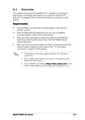
...that your system. n z o n e . ASUS P5ND2-SLI Series 6-1 Requirements • You should have two identical SLI-ready graphics cards that are NVIDIA® certified. • Visit the ASUS website (www.asus.com) for a list of qualified SLI-ready graphics cards for this section. See "15...the installation procedures in this motherboard. • Make sure that your power supply unit (PSU) can provide at least the minimum power required by your graphics card driver supports the NVIDIA SLI technology. ATX power connectors" on page 2-34 for the latest certified graphics card and ...
...that your system. n z o n e . ASUS P5ND2-SLI Series 6-1 Requirements • You should have two identical SLI-ready graphics cards that are NVIDIA® certified. • Visit the ASUS website (www.asus.com) for a list of qualified SLI-ready graphics cards for this section. See "15...the installation procedures in this motherboard. • Make sure that your power supply unit (PSU) can provide at least the minimum power required by your graphics card driver supports the NVIDIA SLI technology. ATX power connectors" on page 2-34 for the latest certified graphics card and ...

P5ND2-SLI Deluxe User's Manual for English Edition
Page 8
...on it by yourself. These devices could interrupt the grounding circuit. • Make sure that your power supply is broken, do not try to or from the motherboard, ensure that all power cables are unplugged. • Seek professional assistance before the signal cables are not sure about the ... devices on a stable surface. • If you are unplugged before using the product, make sure all the manuals that the power cables for the devices are using, contact your local power company. • If the power supply is set to the correct voltage in any damage, contact your area.
...on it by yourself. These devices could interrupt the grounding circuit. • Make sure that your power supply is broken, do not try to or from the motherboard, ensure that all power cables are unplugged. • Seek professional assistance before the signal cables are not sure about the ... devices on a stable surface. • If you are unplugged before using the product, make sure all the manuals that the power cables for the devices are using, contact your local power company. • If the power supply is set to the correct voltage in any damage, contact your area.
P5ND2-SLI Deluxe User's Manual for English Edition
Page 13
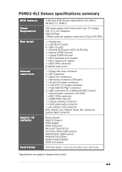
...xiii P5ND2-SLI Deluxe specifications summary BIOS features Power Requirement Rear panel Internal connectors Support CD contents Form Factor 4 MB Flash ROM, Phoenix-Award BIOS, PnP, DMI2.0, SM BIOS 2.3, WfM2.0 ATX power supply (with 24-pin and 4-pin 12 V plugs) ATX 12 V 2.0 compliant ASUS EZ... connector 1 x Chassis intrusion connector 1 x Front panel audio connector 1 x SLI selector card connector CPU, Chassis (x2), Chipset, Power fan connectors System panel connector Device drivers ASUS PC Probe II ASUS Update ASUS AI Booster Microsoft® DirectX 9.0c Anti-Virus Utility (OEM version) WinDVD...
...xiii P5ND2-SLI Deluxe specifications summary BIOS features Power Requirement Rear panel Internal connectors Support CD contents Form Factor 4 MB Flash ROM, Phoenix-Award BIOS, PnP, DMI2.0, SM BIOS 2.3, WfM2.0 ATX power supply (with 24-pin and 4-pin 12 V plugs) ATX 12 V 2.0 compliant ASUS EZ... connector 1 x Chassis intrusion connector 1 x Front panel audio connector 1 x SLI selector card connector CPU, Chassis (x2), Chipset, Power fan connectors System panel connector Device drivers ASUS PC Probe II ASUS Update ASUS AI Booster Microsoft® DirectX 9.0c Anti-Virus Utility (OEM version) WinDVD...

P5ND2-SLI Deluxe User's Manual for English Edition
Page 27
...power supply is ON, in sleep mode, or in softoff mode. This is a reminder that the system is switched off or the p o w e r c o r d i s d e t a c h e d f r o m t h e p o w e r s u p p l y . The illustration below shows the location of the onboard LEDs. ASUS P5ND2-SLI Deluxe... 2-1 The red warning LED lights up to indicate that you should shut down the system and unplug the power cable before handling components to avoid damaging them due to static electricity. • Hold components by...
...power supply is ON, in sleep mode, or in softoff mode. This is a reminder that the system is switched off or the p o w e r c o r d i s d e t a c h e d f r o m t h e p o w e r s u p p l y . The illustration below shows the location of the onboard LEDs. ASUS P5ND2-SLI Deluxe... 2-1 The red warning LED lights up to indicate that you should shut down the system and unplug the power cable before handling components to avoid damaging them due to static electricity. • Hold components by...

P5ND2-SLI Deluxe User's Manual for English Edition
Page 42
... socket. 2 1 DDR2 DIMM notch 2-16 Chapter 2: Hardware information Simultaneously press the retaining clips outward to both the motherboard and the components. 2.4.3 Installing a DIMM Unplug the power supply before adding or removing DIMMs or other system components. To install a DIMM: 1. Firmly insert the DIMM into a socket to avoid damaging the DIMM. • The...
... socket. 2 1 DDR2 DIMM notch 2-16 Chapter 2: Hardware information Simultaneously press the retaining clips outward to both the motherboard and the components. 2.4.3 Installing a DIMM Unplug the power supply before adding or removing DIMMs or other system components. To install a DIMM: 1. Firmly insert the DIMM into a socket to avoid damaging the DIMM. • The...

P5ND2-SLI Deluxe User's Manual for English Edition
Page 60
...8482;; The system may become unstable or may not boot up if the power is recommended when configuring a system with more power-consuming devices. Power supply requirements Components/Peripherals Intel® LGA775 CPU type PCIe™ x16 graphics ...x2 2 2 1 0 1 0 3 > 17A >= 350W EATXPWR ATX12V +3 Volts P5ND2-SLI +12V GND EZ_DET +5V +12 Volts +12V DC +12V DC +12 Volts GND GND +5V Standby Power OK EZ_PLUG Ground +5 Volts Ground +5 Volts ® Ground +3 Volts P5ND2-SLI DELUXE ATX power connectors +3 Volts Ground +5 Volts +5 Volts +5 Volts -5 Volts Ground Ground Ground PSON#...
...8482;; The system may become unstable or may not boot up if the power is recommended when configuring a system with more power-consuming devices. Power supply requirements Components/Peripherals Intel® LGA775 CPU type PCIe™ x16 graphics ...x2 2 2 1 0 1 0 3 > 17A >= 350W EATXPWR ATX12V +3 Volts P5ND2-SLI +12V GND EZ_DET +5V +12 Volts +12V DC +12V DC +12 Volts GND GND +5V Standby Power OK EZ_PLUG Ground +5 Volts Ground +5 Volts ® Ground +3 Volts P5ND2-SLI DELUXE ATX power connectors +3 Volts Ground +5 Volts +5 Volts +5 Volts -5 Volts Ground Ground Ground PSON#...


