User Guide
Page 3
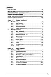
...this guide...viii MAXIMUS VIII EXTREME specifications summary x OC Panel II specifications summary xvi Package contents...xvii Installation tools and components xviii Chapter 1: Product Introduction 1.1 Special features 1-1 1.1.1 Product highlights 1-1 1.1.2 ROG Exclusive Features 1-3 1.1.3 ASUS Special ...your PC system 2-1 2.1.1 Motherboard installation 2-1 2.1.2 CPU installation 2-3 2.1.3 CPU heatsink and fan assembly installation 2-5 2.1.4 DIMM installation 2-7 2.1.5 ATX Power connection 2-8 2.1.6 SATA device connection 2-9 2.1.7 Front I/O Connector 2-10...
...this guide...viii MAXIMUS VIII EXTREME specifications summary x OC Panel II specifications summary xvi Package contents...xvii Installation tools and components xviii Chapter 1: Product Introduction 1.1 Special features 1-1 1.1.1 Product highlights 1-1 1.1.2 ROG Exclusive Features 1-3 1.1.3 ASUS Special ...your PC system 2-1 2.1.1 Motherboard installation 2-1 2.1.2 CPU installation 2-3 2.1.3 CPU heatsink and fan assembly installation 2-5 2.1.4 DIMM installation 2-7 2.1.5 ATX Power connection 2-8 2.1.6 SATA device connection 2-9 2.1.7 Front I/O Connector 2-10...

User Guide
Page 71
To install the CPU heatsink and fan assembly Chapter 2 ASUS MAXIMUS VIII EXTREME 2-5 2.1.3 CPU heatsink and fan assembly installation Apply the Thermal Interface Material to the CPU heatsink and CPU before you install the heatsink and fan, if necessary.
To install the CPU heatsink and fan assembly Chapter 2 ASUS MAXIMUS VIII EXTREME 2-5 2.1.3 CPU heatsink and fan assembly installation Apply the Thermal Interface Material to the CPU heatsink and CPU before you install the heatsink and fan, if necessary.

User Guide
Page 72
To uninstall the CPU heatsink and fan assembly Chapter 2 2-6 Chapter 2: Basic Installation
To uninstall the CPU heatsink and fan assembly Chapter 2 2-6 Chapter 2: Basic Installation

User Guide
Page 88
Secure the OC Panel II and the OC Panel II 5.25-inch drive bay metal case assembly into the drive bay with the two (2) screws. Shut down your computer chassis and remove the front cover of an available 5.25-inch drive bay. 7. ... II fits snugly into the drive bay. 8. Align and insert the OC Panel II and the OC Panel II 5.25-inch drive bay metal case assembly into the OC Panel II 5.25-inch drive bay metal case. 5.
Secure the OC Panel II and the OC Panel II 5.25-inch drive bay metal case assembly into the drive bay with the two (2) screws. Shut down your computer chassis and remove the front cover of an available 5.25-inch drive bay. 7. ... II fits snugly into the drive bay. 8. Align and insert the OC Panel II and the OC Panel II 5.25-inch drive bay metal case assembly into the OC Panel II 5.25-inch drive bay metal case. 5.
User Guide
Page 90
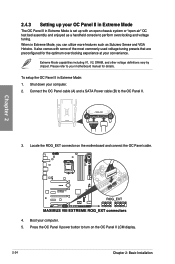
...power button to the OC Panel II. 3. Shut down your computer. 5. When in Extreme Mode, you can utilize more features such as a handheld console to your motherboard manual for.... 2. Chapter 2 4. To setup the OC Panel II in Extreme Mode: 1. It also comes with an open chassis system or "open-air" OC test bed assembly and enjoyed as Subzero Sense and VGA Hotwire. 2.4.3 Setting up your... OC Panel II in Extreme Mode The OC Panel II in Extreme Mode is set up with some of the...
...power button to the OC Panel II. 3. Shut down your computer. 5. When in Extreme Mode, you can utilize more features such as a handheld console to your motherboard manual for.... 2. Chapter 2 4. To setup the OC Panel II in Extreme Mode: 1. It also comes with an open chassis system or "open-air" OC test bed assembly and enjoyed as Subzero Sense and VGA Hotwire. 2.4.3 Setting up your... OC Panel II in Extreme Mode The OC Panel II in Extreme Mode is set up with some of the...
