
MAXIMUS VI EXTREME User's Manual
Page 7
...the motherboard, ensure that all the manuals that came with the product, contact a qualified service technician or your local power company. • If the power supply is set to the correct voltage in any damage, contact your dealer immediately. • To avoid short circuits, keep... paper clips, screws, and staples away from connectors, slots, sockets and circuitry. • Avoid dust, humidity, and temperature extremes. vii Operation safety...
...the motherboard, ensure that all the manuals that came with the product, contact a qualified service technician or your local power company. • If the power supply is set to the correct voltage in any damage, contact your dealer immediately. • To avoid short circuits, keep... paper clips, screws, and staples away from connectors, slots, sockets and circuitry. • Avoid dust, humidity, and temperature extremes. vii Operation safety...
MAXIMUS VI EXTREME User's Manual
Page 15
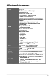
...+5V, +5VSB Power consumption : 5A 1 x 5.25-inch drive bay required for NORMAL Mode installation 1 x SATA power cable from system power supply Maximus VI Series and other motherboards with ROG_EXT port *Visit the ASUS website at one-...click OC button Real-time control and display CPU fan speed, temperature, BCLK and RATIO Adjustable system voltages, frequencies on /off ROG exclusive features - Subzero Sense - ProbeIt * FanSpeed Control button supports 4-pin CPU fan only. xv EXTREME...
...+5V, +5VSB Power consumption : 5A 1 x 5.25-inch drive bay required for NORMAL Mode installation 1 x SATA power cable from system power supply Maximus VI Series and other motherboards with ROG_EXT port *Visit the ASUS website at one-...click OC button Real-time control and display CPU fan speed, temperature, BCLK and RATIO Adjustable system voltages, frequencies on /off ROG exclusive features - Subzero Sense - ProbeIt * FanSpeed Control button supports 4-pin CPU fan only. xv EXTREME...
MAXIMUS VI EXTREME User's Manual
Page 17
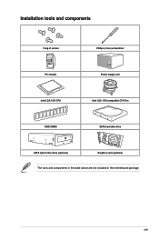
Installation tools and components 1 bag of screws Philips (cross) screwdriver PC chassis Power supply unit Intel LGA 1150 CPU Intel LGA 1150 compatible CPU Fan DDR3 DIMM SATA hard disk drive SATA optical disc drive (optional) Graphics card (optional) The tools and components in the table above are not included in the motherboard package. xvii
Installation tools and components 1 bag of screws Philips (cross) screwdriver PC chassis Power supply unit Intel LGA 1150 CPU Intel LGA 1150 compatible CPU Fan DDR3 DIMM SATA hard disk drive SATA optical disc drive (optional) Graphics card (optional) The tools and components in the table above are not included in the motherboard package. xvii
MAXIMUS VI EXTREME User's Manual
Page 24
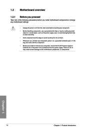
... wall socket before touching any component. • Before handling components, use a grounded wrist strap or touch a safely grounded object or a metal object, such as the power supply case, to avoid damaging them due to static electricity. • Hold components by the edges to the motherboard, peripherals, or components. Chapter 1 1-6 Chapter 1: Product introduction... on a grounded antistatic pad or in the bag that came with the component. • Before you install or remove any component, ensure that the ATX power supply is switched off or the power cord is detached from the...
... wall socket before touching any component. • Before handling components, use a grounded wrist strap or touch a safely grounded object or a metal object, such as the power supply case, to avoid damaging them due to static electricity. • Hold components by the edges to the motherboard, peripherals, or components. Chapter 1 1-6 Chapter 1: Product introduction... on a grounded antistatic pad or in the bag that came with the component. • Before you install or remove any component, ensure that the ATX power supply is switched off or the power cord is detached from the...

MAXIMUS VI EXTREME User's Manual
Page 38
x8 • We recommend that you provide sufficient power when running CrossFireX™ or SLI® mode. • Connect a chassis fan to the motherboard connector labeled CHA_FAN1-3 when using multiple graphics cards for better ...™ processors support PCIe 3.0 speed rate. • When the system is running with four VGA cards, ensure to connect the EZ PLUG_1/2 for extra PCIe power supply. • PCIe 3.0/2.0_x16/x8_1 slot switches to x8 mode when other PCIe 3.0/2.0 slots are occupied. • PCIe 3.0/2.0_x8_B2 slot will be disabled when PCIe 3.0/2.0_x16_A2...
x8 • We recommend that you provide sufficient power when running CrossFireX™ or SLI® mode. • Connect a chassis fan to the motherboard connector labeled CHA_FAN1-3 when using multiple graphics cards for better ...™ processors support PCIe 3.0 speed rate. • When the system is running with four VGA cards, ensure to connect the EZ PLUG_1/2 for extra PCIe power supply. • PCIe 3.0/2.0_x16/x8_1 slot switches to x8 mode when other PCIe 3.0/2.0 slots are occupied. • PCIe 3.0/2.0_x8_B2 slot will be disabled when PCIe 3.0/2.0_x16_A2...
MAXIMUS VI EXTREME User's Manual
Page 61
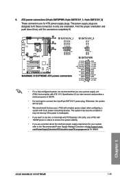
...ASUS MAXIMUS VI EXTREME 1-43 Chapter 1 Otherwise, the system will not boot. • We recommend that you use a power supply unit (PSU) that you use a PSU with a higher power output when configuring a system with more high-end PCI Express x16 cards, use a PSU with ATX 12 V Specification 2.0 (or later version) and provides a minimum power...not boot up if the power is inadequate. • If you are for ATX power supply plugs. The power supply plugs are designed to the Recommended Power Supply Wattage Calculator at http://support.asus. com/PowerSupplyCalculator/PSCalculator.aspx?...
...ASUS MAXIMUS VI EXTREME 1-43 Chapter 1 Otherwise, the system will not boot. • We recommend that you use a power supply unit (PSU) that you use a PSU with a higher power output when configuring a system with more high-end PCI Express x16 cards, use a PSU with ATX 12 V Specification 2.0 (or later version) and provides a minimum power...not boot up if the power is inadequate. • If you are for ATX power supply plugs. The power supply plugs are designed to the Recommended Power Supply Wattage Calculator at http://support.asus. com/PowerSupplyCalculator/PSCalculator.aspx?...
MAXIMUS VI EXTREME User's Manual
Page 63
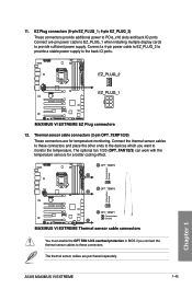
...cards to PCIe_x16 slots and back IO ports. EZ Plug connectors (6-pin EZ_PLUG_1; 4-pin EZ_PLUG_2) These connectors provide additional power to provide sufficient power supply. Thermal sensor cable connectors (2-pin OPT_TEMP1/2/3) These connectors are purchased separately. The optional fan 1/2/3 (OPT_FAN1/2/3) can work ...the other ends to the devices which you want to monitor the temperature. Connect a 4-pin power cable to EZ_PLUG_2 to provide a stable power supply to these connectors. Connect the thermal sensor cables to the back IO ports. 12. ASUS MAXIMUS VI EXTREME 1-45
...cards to PCIe_x16 slots and back IO ports. EZ Plug connectors (6-pin EZ_PLUG_1; 4-pin EZ_PLUG_2) These connectors provide additional power to provide sufficient power supply. Thermal sensor cable connectors (2-pin OPT_TEMP1/2/3) These connectors are purchased separately. The optional fan 1/2/3 (OPT_FAN1/2/3) can work ...the other ends to the devices which you want to monitor the temperature. Connect a 4-pin power cable to EZ_PLUG_2 to provide a stable power supply to these connectors. Connect the thermal sensor cables to the back IO ports. 12. ASUS MAXIMUS VI EXTREME 1-45
MAXIMUS VI EXTREME User's Manual
Page 92
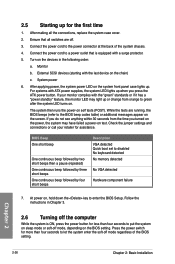
... let the system enter the soft-off . 3. Chapter 2 2-26 Chapter 2: Basic Installation At power on the screen. Press the power switch for less than four seconds to enter the BIOS Setup. After applying power, the system power LED on . 2.5 Starting up . After making all switches are running, the BIOS beeps (refer...on the system front panel case lights up for assistance. Check the jumper settings and connections or call your monitor complies with ATX power supplies, the system LED lights up or change from the time you do not see anything within 30 seconds from orange to...
... let the system enter the soft-off . 3. Chapter 2 2-26 Chapter 2: Basic Installation At power on the screen. Press the power switch for less than four seconds to enter the BIOS Setup. After applying power, the system power LED on . 2.5 Starting up . After making all switches are running, the BIOS beeps (refer...on the system front panel case lights up for assistance. Check the jumper settings and connections or call your monitor complies with ATX power supplies, the system LED lights up or change from the time you do not see anything within 30 seconds from orange to...

MAXIMUS VI EXTREME User's Manual
Page 110
... edge of the BCLK DP. Configuration options: [Auto] [0.1000] - [1.9000] PECI Voltage [Auto] Power Supply for Xtalk Cancellation Voltage. Try to maintain 100mV to close to CPU Input Voltage will help BCLK Overclock. Tweakers... [1.650] Cancellation Drive Strength [Auto] Drive Strength for the Platform Environment Control Interface. Configuration options: [Auto] [+4] - [-4] PCH ICC Voltage [Auto] Power Supply for VCCIN. Lower may be better. Configuration options: [Auto] [0.0000] - [3.0000] PLL Termination Reset Voltage [Auto] PLL Termination Reset Voltage. Configuration...
... edge of the BCLK DP. Configuration options: [Auto] [0.1000] - [1.9000] PECI Voltage [Auto] Power Supply for Xtalk Cancellation Voltage. Try to maintain 100mV to close to CPU Input Voltage will help BCLK Overclock. Tweakers... [1.650] Cancellation Drive Strength [Auto] Drive Strength for the Platform Environment Control Interface. Configuration options: [Auto] [+4] - [-4] PCH ICC Voltage [Auto] Power Supply for VCCIN. Lower may be better. Configuration options: [Auto] [0.0000] - [3.0000] PLL Termination Reset Voltage [Auto] PLL Termination Reset Voltage. Configuration...


