MAXIMUS VI EXTREME User's Manual
Page 4
Profile 3-48 3.9.3 ASUS SPD Information 3-49 3.9.4 BIOS Flashback 3-50 3.10 Exit menu 3-51 iv 2.2 BIOS update utility 2-15 2.3 Motherboard rear and audio connections 2-16 2.3.1 Rear I/O connection 2-16 2.3.2 Audio I/O connections 2-17 2.4 OC Panel...2-21 2.4.1 OC Panel Overview 2-21 2.4.2 Setting up your OC Panel in Normal Mode 2-23 2.4.3 Setting up your OC Panel in Extreme Mode 2-25...
Profile 3-48 3.9.3 ASUS SPD Information 3-49 3.9.4 BIOS Flashback 3-50 3.10 Exit menu 3-51 iv 2.2 BIOS update utility 2-15 2.3 Motherboard rear and audio connections 2-16 2.3.1 Rear I/O connection 2-16 2.3.2 Audio I/O connections 2-17 2.4 OC Panel...2-21 2.4.1 OC Panel Overview 2-21 2.4.2 Setting up your OC Panel in Normal Mode 2-23 2.4.3 Setting up your OC Panel in Extreme Mode 2-25...
MAXIMUS VI EXTREME User's Manual
Page 5
3.11 Updating BIOS 3-52 3.11.1 ASUS EZ Flash 2 3-53 3.11.2 ASUS CrashFree BIOS 3 3-54 3.11.3 ASUS BIOS Updater 3-55 3.12 Secure Erase 3-58 Chapter 4: Software support 4.1 Installing an operating system 4-1 4.2 Support DVD information 4-1 4.2.1 Running the support DVD 4-1 4.2.2 Obtaining the software manuals 4-3 4.3 Software ...
3.11 Updating BIOS 3-52 3.11.1 ASUS EZ Flash 2 3-53 3.11.2 ASUS CrashFree BIOS 3 3-54 3.11.3 ASUS BIOS Updater 3-55 3.12 Secure Erase 3-58 Chapter 4: Software support 4.1 Installing an operating system 4-1 4.2 Support DVD information 4-1 4.2.1 Running the support DVD 4-1 4.2.2 Obtaining the software manuals 4-3 4.3 Software ...
MAXIMUS VI EXTREME User's Manual
Page 8
... by your dealer. It includes description of the standard package. Detailed descriptions of the BIOS parameters are not part of the switches, jumpers, and connectors on ASUS hardware and software products. viii Optional documentation Your product package may have to perform when... installing system components. • Chapter 3: BIOS setup This chapter tells how to change system settings through the BIOS Setup menus. ASUS websites The ASUS website provides updated information on the motherboard. • Chapter 2: Basic Installation This ...
... by your dealer. It includes description of the standard package. Detailed descriptions of the BIOS parameters are not part of the switches, jumpers, and connectors on ASUS hardware and software products. viii Optional documentation Your product package may have to perform when... installing system components. • Chapter 3: BIOS setup This chapter tells how to change system settings through the BIOS Setup menus. ASUS websites The ASUS website provides updated information on the motherboard. • Chapter 2: Basic Installation This ...
MAXIMUS VI EXTREME User's Manual
Page 12
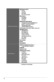
... Erase - Fan Xpert 2 - RC Remote - Extreme Tweaker - USB 3.0 Boost - ROG BIOS Print - O.C. GPU Boost - RC Poster ROG Extreme Engine Digi+ III - Profile - AI Suite III - TurboV EVO - ROG Exclusive Features Special Features ROG Extreme OC Kit - LN2 Mode - RC Diagram - Full digital 8+2 phase CPU/DRAM power - Tweaker's Paradise - ASUS Exclusive Features - DIGI+ Power Control - AI...
... Erase - Fan Xpert 2 - RC Remote - Extreme Tweaker - USB 3.0 Boost - ROG BIOS Print - O.C. GPU Boost - RC Poster ROG Extreme Engine Digi+ III - Profile - AI Suite III - TurboV EVO - ROG Exclusive Features Special Features ROG Extreme OC Kit - LN2 Mode - RC Diagram - Full digital 8+2 phase CPU/DRAM power - Tweaker's Paradise - ASUS Exclusive Features - DIGI+ Power Control - AI...
MAXIMUS VI EXTREME User's Manual
Page 13
... 10 x ProbeIt Measurement Points 1 x LN2 Mode jumper 1 x Slow mode switch 1 x Power-on the next page) xiii ASUS C.P.R. (CPU Parameter Recall) ASUS Q-Design - ASUS Q-DIMM 1 x Clear CMOS button 1 x ROG Connect button 2 x USB 2.0 ports (1 port can be switched to ROG ...Plug connector (in white for back I /O Ports Internal Connectors ASUS EZ DIY - ASUS BIOS Flashback - ASUS CrashFree BIOS 3 - ASUS Q-Shield - ASUS Q-LED (CPU, DRAM, VGA, Boot Device LED) - ASUS EZ Flash 2 - ASUS Q-Slot - ASUS Q-Connector - button 1 x BIOS Switch button 1 x S/PDIF out header (continued on button 1...
... 10 x ProbeIt Measurement Points 1 x LN2 Mode jumper 1 x Slow mode switch 1 x Power-on the next page) xiii ASUS C.P.R. (CPU Parameter Recall) ASUS Q-Design - ASUS Q-DIMM 1 x Clear CMOS button 1 x ROG Connect button 2 x USB 2.0 ports (1 port can be switched to ROG ...Plug connector (in white for back I /O Ports Internal Connectors ASUS EZ DIY - ASUS BIOS Flashback - ASUS CrashFree BIOS 3 - ASUS Q-Shield - ASUS Q-LED (CPU, DRAM, VGA, Boot Device LED) - ASUS EZ Flash 2 - ASUS Q-Slot - ASUS Q-Connector - button 1 x BIOS Switch button 1 x S/PDIF out header (continued on button 1...
MAXIMUS VI EXTREME User's Manual
Page 14
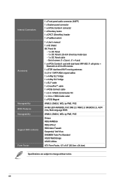
...; cable 1 x ROG Connect cable 1 x 2-in-1 ASUS Q-Connector Kit 1 x 12-in-1 ROG Cable Label 1 x ROG Magnet WfM2.0, DMI2.0, WOL by PME, PXE 64 Mb UEFI AMI BIOS, PnP, DMI 2.0, WfM 2.0, SM BIOS 2.5, ACPI 2.0a, Multi-language BIOS WfM2.0, DMI2.0, WOL by PME, PXE Drivers ROG RAMDisk ... Mem TweakIt Kaspersky® Anti-Virus DAEMON Tools Pro Standard ASUS WebStorage ASUS Utilities ATX Form Factor, 12" x 9.6" (30.5cm x 24.4cm) Specifications are subject to change without notice. Internal Connectors Accessory Manageability BIOS Features Manageability Support DVD contents Form Factor 1 x Front panel...
...; cable 1 x ROG Connect cable 1 x 2-in-1 ASUS Q-Connector Kit 1 x 12-in-1 ROG Cable Label 1 x ROG Magnet WfM2.0, DMI2.0, WOL by PME, PXE 64 Mb UEFI AMI BIOS, PnP, DMI 2.0, WfM 2.0, SM BIOS 2.5, ACPI 2.0a, Multi-language BIOS WfM2.0, DMI2.0, WOL by PME, PXE Drivers ROG RAMDisk ... Mem TweakIt Kaspersky® Anti-Virus DAEMON Tools Pro Standard ASUS WebStorage ASUS Utilities ATX Form Factor, 12" x 9.6" (30.5cm x 24.4cm) Specifications are subject to change without notice. Internal Connectors Accessory Manageability BIOS Features Manageability Support DVD contents Form Factor 1 x Front panel...
MAXIMUS VI EXTREME User's Manual
Page 15
... SATA power cable from system power supply Maximus VI Series and other motherboards with 90 plus-degree-tilt movable faceplate (EXTREME Mode) FanSpeed Control button* - EXTREME Mode for subzero OC benching - Standard/...Silent/Turbo mode Four (4) additional 4-pin fan headers LCM backlight on -the-fly Stylish design with ROG_EXT port *Visit the ASUS...chassis usage Seamless integration with CPU Level Up at www.asus.com for the latest motherboard support/compatibility lists. **Please install the ...
... SATA power cable from system power supply Maximus VI Series and other motherboards with 90 plus-degree-tilt movable faceplate (EXTREME Mode) FanSpeed Control button* - EXTREME Mode for subzero OC benching - Standard/...Silent/Turbo mode Four (4) additional 4-pin fan headers LCM backlight on -the-fly Stylish design with ROG_EXT port *Visit the ASUS...chassis usage Seamless integration with CPU Level Up at www.asus.com for the latest motherboard support/compatibility lists. **Please install the ...
MAXIMUS VI EXTREME User's Manual
Page 20
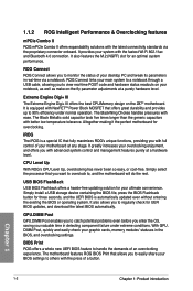
...problems even before you enter the OS, saving you want to overclock to 90% efficiency under extreme conditions. BIOS Print ROG offers a whole new UEFI BIOS feature to monitor the status of your BIOS settings to easily share your motherboard at a hardware level. Simply select the processor that offers ... the demands of a button. ROG Connect ROG Connect allows you with the fastest Wi-Fi 802.11ac and Bluetooth 4.0 connection. Extreme Engine Digi+ III The Extreme Engine Digi+ III offers the best CPU/Memory design on your main system to a notebook through a USB cable, allowing you ...
...problems even before you enter the OS, saving you want to overclock to 90% efficiency under extreme conditions. BIOS Print ROG offers a whole new UEFI BIOS feature to monitor the status of your BIOS settings to easily share your motherboard at a hardware level. Simply select the processor that offers ... the demands of a button. ROG Connect ROG Connect allows you with the fastest Wi-Fi 802.11ac and Bluetooth 4.0 connection. Extreme Engine Digi+ III The Extreme Engine Digi+ III offers the best CPU/Memory design on your main system to a notebook through a USB cable, allowing you ...
MAXIMUS VI EXTREME User's Manual
Page 21
...stop shop to super-cool liquid thermal temp readings and streamlined hardware-level GPU overvolting. With one saved BIOS from the previous version. Extreme Tweaker Extreme Tweaker is the next step in dedicated direct tweaking. The Loadline Calibration ensures stable and optimal CPU ...features normal mode with the BIOS, OS, or software utilities. Loadline Calibration Maintaining ample voltage support for the tweaked overclocking setting, and one press of the CPU Level Up button you field access to fine-tune your system's current voltage. Chapter 1 ASUS MAXIMUS VI EXTREME 1-3
...stop shop to super-cool liquid thermal temp readings and streamlined hardware-level GPU overvolting. With one saved BIOS from the previous version. Extreme Tweaker Extreme Tweaker is the next step in dedicated direct tweaking. The Loadline Calibration ensures stable and optimal CPU ...features normal mode with the BIOS, OS, or software utilities. Loadline Calibration Maintaining ample voltage support for the tweaked overclocking setting, and one press of the CPU Level Up button you field access to fine-tune your system's current voltage. Chapter 1 ASUS MAXIMUS VI EXTREME 1-3
MAXIMUS VI EXTREME User's Manual
Page 26
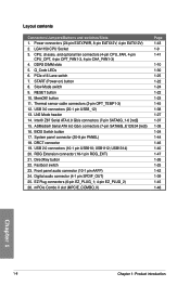
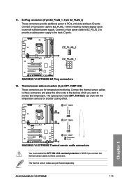
... 1 1-8 Chapter 1: Product introduction EZ Plug connectors (6-pin EZ_PLUG_1; 4-pin EZ_PLUG_2) 26. ROG Extension connector (18-1 pin ROG_EXT) 21. Fastboot switch 23. PCIe x16 Lane switch 7. BIOS Switch button 17. Thermal sensor cable connectors (2-pin OPT_TEMP1-3) 12. Q_Code LEDs 6. Layout contents Connectors/Jumpers/Buttons and switches/Slots 1. RESET button 10.
... 1 1-8 Chapter 1: Product introduction EZ Plug connectors (6-pin EZ_PLUG_1; 4-pin EZ_PLUG_2) 26. ROG Extension connector (18-1 pin ROG_EXT) 21. Fastboot switch 23. PCIe x16 Lane switch 7. BIOS Switch button 17. Thermal sensor cable connectors (2-pin OPT_TEMP1-3) 12. Q_Code LEDs 6. Layout contents Connectors/Jumpers/Buttons and switches/Slots 1. RESET button 10.

MAXIMUS VI EXTREME User's Manual
Page 36
...M378B5273CH0-CH9 4GB DS SAMSUNG SP002GBLTU133V02 2GB SS S-POWER - C2S46D30-D313 D9PFJ - Voltage - settings in the BIOS for the hyper DIMM support. • Visit the ASUS website for better compatibility. (4) Supports four (4) modules inserted into any slot as one pair of individual CPUs...(1) Supports one (1) module inserted into both the red and black slots as two pairs of Dual-channel memory configuration. • ASUS exclusively provides hyper DIMM support function. • Hyper DIMM support is subject to the physical characteristics of Dual-channel memory configuration....
...M378B5273CH0-CH9 4GB DS SAMSUNG SP002GBLTU133V02 2GB SS S-POWER - C2S46D30-D313 D9PFJ - Voltage - settings in the BIOS for the hyper DIMM support. • Visit the ASUS website for better compatibility. (4) Supports four (4) modules inserted into any slot as one pair of individual CPUs...(1) Supports one (1) module inserted into both the red and black slots as two pairs of Dual-channel memory configuration. • ASUS exclusively provides hyper DIMM support function. • Hyper DIMM support is subject to the physical characteristics of Dual-channel memory configuration....
MAXIMUS VI EXTREME User's Manual
Page 41
... continues memory tuning after turning on the ASUS website at www.asus.com after the whole tuning process, the DRAM_LED lights continuously. ASUS MAXIMUS VI EXTREME 1-23 Chapter 1 Turn off the computer and replace DIMMs during POST reminding you that the BIOS has been restored to its default settings.... test the next set of the DRAM_LED increases, indicating different test processes. • Due to the latest BIOS version from the ASUS website at www.asus.com. • If you download and update to memory tuning requirement, the system automatically reboots when each timing...
... continues memory tuning after turning on the ASUS website at www.asus.com after the whole tuning process, the DRAM_LED lights continuously. ASUS MAXIMUS VI EXTREME 1-23 Chapter 1 Turn off the computer and replace DIMMs during POST reminding you that the BIOS has been restored to its default settings.... test the next set of the DRAM_LED increases, indicating different test processes. • Due to the latest BIOS version from the ASUS website at www.asus.com. • If you download and update to memory tuning requirement, the system automatically reboots when each timing...
MAXIMUS VI EXTREME User's Manual
Page 42
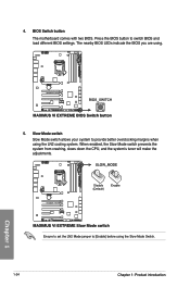
... 1 Ensure to set the LN2 Mode jumper to [Enable] before using . 5. Slow Mode switch Slow Mode switch allows your system to switch BIOS and load different BIOS settings. Press the BIOS button to provide better overclocking margins when using the LN2 cooling system. When enabled, the Slow Mode switch prevents the system from...
... 1 Ensure to set the LN2 Mode jumper to [Enable] before using . 5. Slow Mode switch Slow Mode switch allows your system to switch BIOS and load different BIOS settings. Press the BIOS button to provide better overclocking margins when using the LN2 cooling system. When enabled, the Slow Mode switch prevents the system from...
MAXIMUS VI EXTREME User's Manual
Page 44
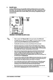
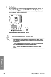
... you reboot your system. • Refer to save your data before using the power-on button to allow your system and conveniently enter the BIOS during POST. DirectKey button This feature allows your system will shut down. Ensure to section 3.8 Boot Menu for details about setting the DirectKey default function.... you to turn on or turn off your system using the DirectKey button. • When the system is on button to reboot and enter the BIOS directly. • Turn off your system to go to press the key during boot-up. It also allows you press the DirectKey button, your ...
... you reboot your system. • Refer to save your data before using the power-on button to allow your system and conveniently enter the BIOS during POST. DirectKey button This feature allows your system will shut down. Ensure to section 3.8 Boot Menu for details about setting the DirectKey default function.... you to turn on or turn off your system using the DirectKey button. • When the system is on button to reboot and enter the BIOS directly. • Turn off your system to go to press the key during boot-up. It also allows you press the DirectKey button, your ...
MAXIMUS VI EXTREME User's Manual
Page 48
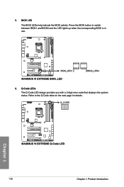
BIOS LED The BIOS LEDs help indicate the BIOS activity. Chapter 1 1-30 Chapter 1: Product introduction Refer to switch between BIOS1 and BIOS2 and the LED lights up when the corresponding BIOS is in use. 6. Q-Code LEDs The Q-Code LED design provides you with a 2-digit error code that displays the system status. Press the BIOS button to the Q-Code table on the next page for details. 5.
BIOS LED The BIOS LEDs help indicate the BIOS activity. Chapter 1 1-30 Chapter 1: Product introduction Refer to switch between BIOS1 and BIOS2 and the LED lights up when the corresponding BIOS is in use. 6. Q-Code LEDs The Q-Code LED design provides you with a 2-digit error code that displays the system status. Press the BIOS button to the Q-Code table on the next page for details. 5.

MAXIMUS VI EXTREME User's Manual
Page 55
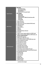
Intel® Z87 Serial ATA 6.0 Gb/s connectors (7-pin SATA6G_1-6 [red]) These connectors connect to [AHCI Mode] by default. ASUS MAXIMUS VI EXTREME 1-37 If you can create a RAID 0, 1, 5, and 10 configuration with the Intel® Rapid Storage Technology through the onboard Intel® Z87... 5.1 RAID configurations or the manual bundled in the motherboard support DVD. • When using these connectors, set the SATA Mode in the BIOS to section 3.6.3 SATA Configuration for details. If you installed Serial ATA hard disk drives, you intend to create a Serial ATA RAID set ...
Intel® Z87 Serial ATA 6.0 Gb/s connectors (7-pin SATA6G_1-6 [red]) These connectors connect to [AHCI Mode] by default. ASUS MAXIMUS VI EXTREME 1-37 If you can create a RAID 0, 1, 5, and 10 configuration with the Intel® Rapid Storage Technology through the onboard Intel® Z87... 5.1 RAID configurations or the manual bundled in the motherboard support DVD. • When using these connectors, set the SATA Mode in the BIOS to section 3.6.3 SATA Configuration for details. If you installed Serial ATA hard disk drives, you intend to create a Serial ATA RAID set ...
MAXIMUS VI EXTREME User's Manual
Page 60
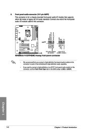
... you want to connect a high-definition or an AC'97 front panel audio module to this connector, set the Front Panel Type item in the BIOS setup to [HD] or [AC97]. Front panel audio connector (10-1 pin AAFP) This connector is for a chassis-mounted front panel audio I /O module cable to this...
... you want to connect a high-definition or an AC'97 front panel audio module to this connector, set the Front Panel Type item in the BIOS setup to [HD] or [AC97]. Front panel audio connector (10-1 pin AAFP) This connector is for a chassis-mounted front panel audio I /O module cable to this...
MAXIMUS VI EXTREME User's Manual
Page 62
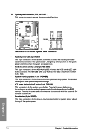
.... The system power LED lights up or flashes when data is for the system power button. Pressing the power button turns the system on the BIOS settings. The speaker allows you turn on the system power, and blinks when the system is in sleep or soft-off button (2-pin PWRSW) This...
.... The system power LED lights up or flashes when data is for the system power button. Pressing the power button turns the system on the BIOS settings. The speaker allows you turn on the system power, and blinks when the system is in sleep or soft-off button (2-pin PWRSW) This...
MAXIMUS VI EXTREME User's Manual
Page 63
...a stable power supply to provide sufficient power supply. The optional fan 1/2/3 (OPT_FAN1/2/3) can work with the temperature sensors for temperature monitoring. ASUS MAXIMUS VI EXTREME 1-45 11. Thermal sensor cable connectors (2-pin OPT_TEMP1/2/3) These connectors are purchased separately. The thermal sensor cables are for a better cooling ... display cards to the back IO ports. 12. Chapter 1 You must enable the OPT FAN 1/2/3 overheat protection in BIOS if you connect the thermal sensor cables to these connectors and place the other ends to the devices which you want ...
...a stable power supply to provide sufficient power supply. The optional fan 1/2/3 (OPT_FAN1/2/3) can work with the temperature sensors for temperature monitoring. ASUS MAXIMUS VI EXTREME 1-45 11. Thermal sensor cable connectors (2-pin OPT_TEMP1/2/3) These connectors are purchased separately. The thermal sensor cables are for a better cooling ... display cards to the back IO ports. 12. Chapter 1 You must enable the OPT FAN 1/2/3 overheat protection in BIOS if you connect the thermal sensor cables to these connectors and place the other ends to the devices which you want ...
MAXIMUS VI EXTREME User's Manual
Page 65
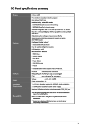
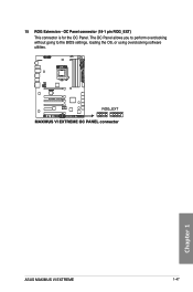
Chapter 1 ASUS MAXIMUS VI EXTREME 1-47 The OC Panel allows you to perform overclocking without going to the BIOS settings, loading the OS, or using overclocking software utilities. 15 ROG Extension - OC Panel connector (18-1 pin ROG_EXT) This connector is for the OC Panel.
Chapter 1 ASUS MAXIMUS VI EXTREME 1-47 The OC Panel allows you to perform overclocking without going to the BIOS settings, loading the OS, or using overclocking software utilities. 15 ROG Extension - OC Panel connector (18-1 pin ROG_EXT) This connector is for the OC Panel.


