
MAXIMUS V EXTREME User's Manual
Page 13
ASUS Q-DIMM 1 x Thunderbolt port 1 x Clear CMOS button 1 x ROG Connect On/Off button 4 x USB 2.0 (1 port for ROG Connect) 1 xPS/2 keyboard/mouse combo port 4 x USB 3.0 ports [blue] 1 x Optical S/PDIF IN... 6-pin EZ Plug connector [black] (for PCIe slots) 1 x 4-pin EZ Plug connector [white] (for back I /O Ports Internal Connectors ASUS Q-Design - ASUS Q-Shield - ASUS Q-LED (CPU, DRAM, VGA, Boot Device LED) - ASUS Q-Connector - ASUS Q-Slot - MAXIMUS V EXTREME specifications summary Special Features Back I /O and PCIe slots) 1 x LN2 Mode header 1 x Slow mode switch 1 x START (Power-on)...
ASUS Q-DIMM 1 x Thunderbolt port 1 x Clear CMOS button 1 x ROG Connect On/Off button 4 x USB 2.0 (1 port for ROG Connect) 1 xPS/2 keyboard/mouse combo port 4 x USB 3.0 ports [blue] 1 x Optical S/PDIF IN... 6-pin EZ Plug connector [black] (for PCIe slots) 1 x 4-pin EZ Plug connector [white] (for back I /O Ports Internal Connectors ASUS Q-Design - ASUS Q-Shield - ASUS Q-LED (CPU, DRAM, VGA, Boot Device LED) - ASUS Q-Connector - ASUS Q-Slot - MAXIMUS V EXTREME specifications summary Special Features Back I /O and PCIe slots) 1 x LN2 Mode header 1 x Slow mode switch 1 x START (Power-on)...

MAXIMUS V EXTREME User's Manual
Page 88
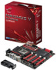
... S/PDIF IN port 14. USB 2.0 port 4, also ROG Connect port 9. Audio I /O connection Rear panel connectors 1. Intel USB 3.0 ports, support ASUS USB 3.0 Boost Turbo Mode 13. Intel Thunderbolt port 6. Clear CMOS button 2. ASMedia USB 3.0 ports, support ASUS USB 3.0 Boost UASP Mode 10. Optical S/PDIF OUT port 4. 2.3 Motherboard rear and audio connections 2.3.1 Rear I /O ports** * and ** : Refer...
... S/PDIF IN port 14. USB 2.0 port 4, also ROG Connect port 9. Audio I /O connection Rear panel connectors 1. Intel USB 3.0 ports, support ASUS USB 3.0 Boost Turbo Mode 13. Intel Thunderbolt port 6. Clear CMOS button 2. ASMedia USB 3.0 ports, support ASUS USB 3.0 Boost UASP Mode 10. Optical S/PDIF OUT port 4. 2.3 Motherboard rear and audio connections 2.3.1 Rear I /O ports** * and ** : Refer...

MAXIMUS V EXTREME User's Manual
Page 98
... Press ++ simultaneously. • Press the reset button on the system chassis. • Press the power button to erase the RTC RAM via the Clear CMOS button. • The BIOS setup program does not support the bluetooth devices. Chapter 3 3-2 Chapter 3: BIOS setup See section 1.2.6 Onboard buttons and .... See section 3.9 Exit Menu for details. • If the system fails to boot after changing any BIOS setting, try to clear the CMOS and reset the motherboard to ensure system compatibility and stability. Entering BIOS at startup To enter BIOS Setup at startup: • Press...
... Press ++ simultaneously. • Press the reset button on the system chassis. • Press the power button to erase the RTC RAM via the Clear CMOS button. • The BIOS setup program does not support the bluetooth devices. Chapter 3 3-2 Chapter 3: BIOS setup See section 1.2.6 Onboard buttons and .... See section 3.9 Exit Menu for details. • If the system fails to boot after changing any BIOS setting, try to clear the CMOS and reset the motherboard to ensure system compatibility and stability. Entering BIOS at startup To enter BIOS Setup at startup: • Press...

MAXIMUS V EXTREME User's Manual
Page 116
... BIOS password. See section 1.2.6 Onboard buttons and switches for information on how to erase the RTC RAM via the Clear CMOS button. • The Administrator or User Password items on top of the basic system information, and allows you to change the system security settings. • ...
... BIOS password. See section 1.2.6 Onboard buttons and switches for information on how to erase the RTC RAM via the Clear CMOS button. • The Administrator or User Password items on top of the basic system information, and allows you to change the system security settings. • ...


