
User Guide
Page 40
...: 1. Make sure that you have properly applied Thermal Interface Material to the CPU heatsink or CPU before you install the heatsink and fan assembly. Narrow end of the groove Motherboard hole Fastener Make sure to orient each fastener with the narrow end of the installed CPU, making sure... top of the groove pointing outward. (The photo shows the groove shaded for emphasis.) 2-12 Chapter 2: Hardware information Orient the heatsink and fan assembly such that the CPU fan cable is closest to the CPU fan connector. Place the heatsink on the motherboard. If you buy a boxed Intel&#...
...: 1. Make sure that you have properly applied Thermal Interface Material to the CPU heatsink or CPU before you install the heatsink and fan assembly. Narrow end of the groove Motherboard hole Fastener Make sure to orient each fastener with the narrow end of the installed CPU, making sure... top of the groove pointing outward. (The photo shows the groove shaded for emphasis.) 2-12 Chapter 2: Hardware information Orient the heatsink and fan assembly such that the CPU fan cable is closest to the CPU fan connector. Place the heatsink on the motherboard. If you buy a boxed Intel&#...
User Guide
Page 41
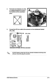
2. CPU_FAN GND CPU FAN PWR CPU FAN IN CPU FAN PWM ® MAXIMUS EXTREME MAXIMUS EXTREME CPU fan connector DO NOT forget to plug this connector. Hardware monitoring errors will occur if you fail to connect the CPU fan connector! A A A B B B A 3. Push down two fasteners at a time in a diagonal sequence to the connector on the motherboard labeled CPU_FAN. Connect the CPU fan cable to secure the heatsink and fan assembly in B place. ASUS Maximus Extreme 2-13
2. CPU_FAN GND CPU FAN PWR CPU FAN IN CPU FAN PWM ® MAXIMUS EXTREME MAXIMUS EXTREME CPU fan connector DO NOT forget to plug this connector. Hardware monitoring errors will occur if you fail to connect the CPU fan connector! A A A B B B A 3. Push down two fasteners at a time in a diagonal sequence to the connector on the motherboard labeled CPU_FAN. Connect the CPU fan cable to secure the heatsink and fan assembly in B place. ASUS Maximus Extreme 2-13
User Guide
Page 42
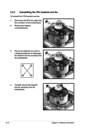
Carefully remove the heatsink and fan assembly from B the motherboard. Rotate each fastener counterclockwise. 3. Pull up two fasteners at a time in a diagonal sequence to disengage the heatsink and fan assembly from the motherboard. 2-14 Chapter 2: Hardware information A A B A B B A 4. 2.3.3 Uninstalling the CPU heatsink and fan To uninstall the CPU heatsink and fan: 1. Disconnect the CPU fan cable from the connector on the motherboard. 2.
Carefully remove the heatsink and fan assembly from B the motherboard. Rotate each fastener counterclockwise. 3. Pull up two fasteners at a time in a diagonal sequence to disengage the heatsink and fan assembly from the motherboard. 2-14 Chapter 2: Hardware information A A B A B B A 4. 2.3.3 Uninstalling the CPU heatsink and fan To uninstall the CPU heatsink and fan: 1. Disconnect the CPU fan cable from the connector on the motherboard. 2.

User Guide
Page 65
... is on the heatpipe assembly. Digital audio connector (4-1 pin SPDIF, for an additional Sony/Philips Digital Interface (S/PDIF) port(s). If you are using ASUS HDMI-equipped graphics card, connect the HDMI card to this connector with a S/PDIF out cable. ® MAXIMUS EXTREME SPDIF_OUT GND SPDIFOUT +5V MAXIMUS EXTREME Digital audio connector The ASUS HDMI-equipped graphics card...
... is on the heatpipe assembly. Digital audio connector (4-1 pin SPDIF, for an additional Sony/Philips Digital Interface (S/PDIF) port(s). If you are using ASUS HDMI-equipped graphics card, connect the HDMI card to this connector with a S/PDIF out cable. ® MAXIMUS EXTREME SPDIF_OUT GND SPDIFOUT +5V MAXIMUS EXTREME Digital audio connector The ASUS HDMI-equipped graphics card...
User Guide
Page 69
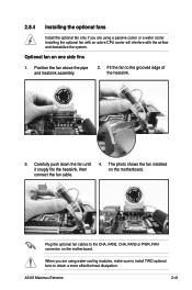
...active CPU cooler will interfere with the airflow and destabilize the system. Optional fan on the motherboard. Position the fan above the pipe and heatsink assembly. 2. When you are using a passive cooler or a water cooler. 2.8.4 Installing the optional fans Install the optional fan only if you ... PWR_FAN connector on the motherboard. Carefully push down the fan until it snugly fits the heatsink, then connect the fan cable. 4. ASUS Maximus Extreme 2-41 The photo shows the fan installed on one side fins 1. Plug the optional fan cables to the grooved edge of the heatsink. 3....
...active CPU cooler will interfere with the airflow and destabilize the system. Optional fan on the motherboard. Position the fan above the pipe and heatsink assembly. 2. When you are using a passive cooler or a water cooler. 2.8.4 Installing the optional fans Install the optional fan only if you ... PWR_FAN connector on the motherboard. Carefully push down the fan until it snugly fits the heatsink, then connect the fan cable. 4. ASUS Maximus Extreme 2-41 The photo shows the fan installed on one side fins 1. Plug the optional fan cables to the grooved edge of the heatsink. 3....
User Guide
Page 71
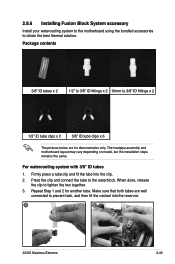
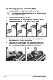
Firmly press a tube clip and fit the tube into the reservoir. 1 2 ASUS Maximus Extreme 2-43 Package contents 3/8" ID tubes x 2 1/2" to 3/8" ID fittings x 2 10mm to 3/8" ID fittings x 2 1/2" ID tube clips x 2 3/8" ID tube clips x 6 The pictures below are well connected to the waterblock. The heatpipe assembly and motherboard layout may vary depending on model, but the installation...
Firmly press a tube clip and fit the tube into the reservoir. 1 2 ASUS Maximus Extreme 2-43 Package contents 3/8" ID tubes x 2 1/2" to 3/8" ID fittings x 2 10mm to 3/8" ID fittings x 2 1/2" ID tube clips x 2 3/8" ID tube clips x 6 The pictures below are well connected to the waterblock. The heatpipe assembly and motherboard layout may vary depending on model, but the installation...
User Guide
Page 72
... with tube clips. Your watercooling system may come with 1/2" or 10mm ID tubes 1. Use the clips to the waterblock. Press the clip and connect the assembled tube to fasten the fittings and the tubes together. 2. The picture shows a watercooling system installed to tighten the two together. 6. When done, release the clip...
... with tube clips. Your watercooling system may come with 1/2" or 10mm ID tubes 1. Use the clips to the waterblock. Press the clip and connect the assembled tube to fasten the fittings and the tubes together. 2. The picture shows a watercooling system installed to tighten the two together. 6. When done, release the clip...
