User Manual
Page 8
... are not damaged. Detailed descriptions of the motherboard and the new technology it supports. • Chapter 2: BIOS information This chapter tells how to change system settings through the BIOS Setup menus. This motherboard should only be used in any damage, contact your retailer. Do not place the product in environments with ambient temperatures...
... are not damaged. Detailed descriptions of the motherboard and the new technology it supports. • Chapter 2: BIOS information This chapter tells how to change system settings through the BIOS Setup menus. This motherboard should only be used in any damage, contact your retailer. Do not place the product in environments with ambient temperatures...

User Manual
Page 17
...in line with the component. • Before you should shut down and reboot the system, and the BIOS automatically restores the CPU parameters to their default settings. ASUS M4A785T-M 1-5 Simply shut down the system and unplug the power cable before touching any component. • Before ...handling components, use of the onboard LED. feature automatically restores the CPU default settings when the system hangs due ...
...in line with the component. • Before you should shut down and reboot the system, and the BIOS automatically restores the CPU parameters to their default settings. ASUS M4A785T-M 1-5 Simply shut down the system and unplug the power cable before touching any component. • Before ...handling components, use of the onboard LED. feature automatically restores the CPU default settings when the system hangs due ...

User Manual
Page 29
... and change the necessary BIOS settings, if any. Failure to do not need to use . 4. Replace the system cover. 1.8.2 Configuring an expansion card After installing the expansion card, configure it and make the necessary hardware settings for later use . ASUS M4A785T-M 1-17 Remove the ...bracket opposite the slot that complies with it by adjusting the software settings. 1. Otherwise, conflicts will arise between the two PCI groups, making the...
... and change the necessary BIOS settings, if any. Failure to do not need to use . 4. Replace the system cover. 1.8.2 Configuring an expansion card After installing the expansion card, configure it and make the necessary hardware settings for later use . ASUS M4A785T-M 1-17 Remove the ...bracket opposite the slot that complies with it by adjusting the software settings. 1. Otherwise, conflicts will arise between the two PCI groups, making the...

User Manual
Page 30
..., remove the onboard battery and move the cap back to reenter data. You can automatically reset parameter settings to clear the CMOS RTC RAM data. Shut down the key during the boot process and enter BIOS setup to pins 1-2. 3. Plug the power cord and turn ON the computer. 4. Move the jumper cap...cell battery powers the RAM data in CMOS. Turn OFF the computer and unplug the power cord. 2. Hold down and reboot the system so the BIOS can clear the CMOS memory of date, time, and system setup parameters by erasing the CMOS RTC RAM data. For system failure due to pins...
..., remove the onboard battery and move the cap back to reenter data. You can automatically reset parameter settings to clear the CMOS RTC RAM data. Shut down the key during the boot process and enter BIOS setup to pins 1-2. 3. Plug the power cord and turn ON the computer. 4. Move the jumper cap...cell battery powers the RAM data in CMOS. Turn OFF the computer and unplug the power cord. 2. Hold down and reboot the system so the BIOS can clear the CMOS memory of date, time, and system setup parameters by erasing the CMOS RTC RAM data. For system failure due to pins...

User Manual
Page 36
...floppy disk drive when installing Windows® XP operating system on a hard disk drive that includes a RAID/AHCI set the SATA Port1-Port4 and SATA Port5-Port6 items in the BIOS to the RAID/AHCI Supplementary Guide included in the folder named Manual in the support DVD. 1-24 Chapter 1: Product...Install the Windows® XP Service Pack 1 or later versions before using Serial ATA. • If you intend to create a Serial ATA RAID set using these connectors, set . • Due to Windows® XP limitation, Windows® XP may not recognize the USB floppy disk drive. • For more details...
...floppy disk drive when installing Windows® XP operating system on a hard disk drive that includes a RAID/AHCI set the SATA Port1-Port4 and SATA Port5-Port6 items in the BIOS to the RAID/AHCI Supplementary Guide included in the folder named Manual in the support DVD. 1-24 Chapter 1: Product...Install the Windows® XP Service Pack 1 or later versions before using Serial ATA. • If you intend to create a Serial ATA RAID set using these connectors, set . • Due to Windows® XP limitation, Windows® XP may not recognize the USB floppy disk drive. • For more details...

User Manual
Page 37
... system is ON turns the system OFF. • Reset button (2-pin RESET) This 2-pin connector is for the system power LED. ASUS M4A785T-M 1-25 The speaker allows you turn on the BIOS settings. System panel connector (20-8 pin PANEL) This connector supports several chassis-mounted functions. • System power LED (2-pin PLED) This 2-pin...
... system is ON turns the system OFF. • Reset button (2-pin RESET) This 2-pin connector is for the system power LED. ASUS M4A785T-M 1-25 The speaker allows you turn on the BIOS settings. System panel connector (20-8 pin PANEL) This connector supports several chassis-mounted functions. • System power LED (2-pin PLED) This 2-pin...
User Manual
Page 39
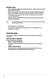
... the motherboard high-definition audio capability. • If you want to connect a high definition front panel audio module to this connector, set the Front Panel Select item in the BIOS to [HD Audio]. The S/PDIF module is VIA High Definition Audio (the name may be different based on the OS). Connect one... SPDIF_OUT) This connector is purchased separately. Go to Start > Control Panel > Sounds and Audio Devices > Sound Playback to avail of Sound playback is purchased separately. 8. ASUS M4A785T-M 1-27
... the motherboard high-definition audio capability. • If you want to connect a high definition front panel audio module to this connector, set the Front Panel Select item in the BIOS to [HD Audio]. The S/PDIF module is VIA High Definition Audio (the name may be different based on the OS). Connect one... SPDIF_OUT) This connector is purchased separately. Go to Start > Control Panel > Sounds and Audio Devices > Sound Playback to avail of Sound playback is purchased separately. 8. ASUS M4A785T-M 1-27

User Manual
Page 45
...load the BIOS default settings to the floppy disk drive, if supported. 3. Refer to restore the BIOS file when it fails or gets corrupted during the updating process. • This function supports USB flash disks with motherboard models. Recovering the BIOS To recover the BIOS: 1. ...system boot failure! 2.1.3 ASUS CrashFree BIOS The ASUS CrashFree BIOS is an auto recovery tool that contains the updated BIOS file. • The BIOS file in the support DVD may not be the latest version. ASUS M4A785T-M 2-3 Download the latest BIOS file from the ASUS website at www.asus.com. • ...
...load the BIOS default settings to the floppy disk drive, if supported. 3. Refer to restore the BIOS file when it fails or gets corrupted during the updating process. • This function supports USB flash disks with motherboard models. Recovering the BIOS To recover the BIOS: 1. ...system boot failure! 2.1.3 ASUS CrashFree BIOS The ASUS CrashFree BIOS is an auto recovery tool that contains the updated BIOS file. • The BIOS file in the support DVD may not be the latest version. ASUS M4A785T-M 2-3 Download the latest BIOS file from the ASUS website at www.asus.com. • ...

User Manual
Page 46
... ASUS website at startup: • Press during the Power-On Self-Test (POST) to download the latest BIOS file for this option only if you can enable the security password feature or change the configuration of the SPI chip. Entering BIOS Setup after POST To enter BIOS Setup after changing any BIOS settings, load the default settings...
... ASUS website at startup: • Press during the Power-On Self-Test (POST) to download the latest BIOS file for this option only if you can enable the security password feature or change the configuration of the SPI chip. Entering BIOS Setup after POST To enter BIOS Setup after changing any BIOS settings, load the default settings...

User Manual
Page 47
...special functions Exit For selecting the exit options and loading default settings. Select Screen Select Item +- 2.2.1 BIOS menu screen Menu items Menu bar Configuration fields Main Advanced Power BIOS SETUP UTILITY Boot Tools Exit Main Settings System Time [19:34:30] System Date [Thu 01/...] :[Not Detected] System Information General help Use [ENTER], [TAB] or [SHIFT-TAB] to select items in the menu and change the settings. ASUS M4A785T-M 2-5 Use the navigation keys to select a field. To select an item on the menu bar, press the right or left arrow key...
...special functions Exit For selecting the exit options and loading default settings. Select Screen Select Item +- 2.2.1 BIOS menu screen Menu items Menu bar Configuration fields Main Advanced Power BIOS SETUP UTILITY Boot Tools Exit Main Settings System Time [19:34:30] System Date [Thu 01/...] :[Not Detected] System Information General help Use [ENTER], [TAB] or [SHIFT-TAB] to select items in the menu and change the settings. ASUS M4A785T-M 2-5 Use the navigation keys to select a field. To select an item on the menu bar, press the right or left arrow key...

User Manual
Page 49
...] This item only appears in the system. ASUS M4A785T-M 2-7 Select Screen Select Item +- These items show Not Detected if no IDE/SATA device is either a ZIP, LS-120, or MO drive. Setting this item to select a field. These values are specifically configuring a CD-ROM drive. The BIOS automatically detects the values opposite the dimmed...
...] This item only appears in the system. ASUS M4A785T-M 2-7 Select Screen Select Item +- These items show Not Detected if no IDE/SATA device is either a ZIP, LS-120, or MO drive. Setting this item to select a field. These values are specifically configuring a CD-ROM drive. The BIOS automatically detects the values opposite the dimmed...

User Manual
Page 50
LBA/Large Mode [Auto] Enables or disables the LBA mode. When this item is set to [Auto], the data transfer from and to use SATA 5~6 before entering OS. 2-8 Chapter 2: BIOS information Select an item then press to [IDE]. Setting this item to [Auto] enables the LBA mode if the device supports this item to...
LBA/Large Mode [Auto] Enables or disables the LBA mode. When this item is set to [Auto], the data transfer from and to use SATA 5~6 before entering OS. 2-8 Chapter 2: BIOS information Select an item then press to [IDE]. Setting this item to [Auto] enables the LBA mode if the device supports this item to...

User Manual
Page 51
Select Screen Select Item +- The BIOS automatically detects the items in this menu. Take caution when changing the settings of the general system specifications. Processor Displays the auto-detected CPU specification. System Memory Displays ...vary depending on the AMD CPU type. Configuration options: [Manual] [Auto] [Overclock Profile] [Test Mode] ASUS M4A785T-M 2-9 Main Advanced Advanced Settings Power BIOS SETUP UTILITY Boot Tools Exit JumperFree Configuration CPU Configuration Chipset Onboard Devices Configuration PCIPnP USB Configuration Adjust System Frequency/Voltage...
Select Screen Select Item +- The BIOS automatically detects the items in this menu. Take caution when changing the settings of the general system specifications. Processor Displays the auto-detected CPU specification. System Memory Displays ...vary depending on the AMD CPU type. Configuration options: [Manual] [Auto] [Overclock Profile] [Test Mode] ASUS M4A785T-M 2-9 Main Advanced Advanced Settings Power BIOS SETUP UTILITY Boot Tools Exit JumperFree Configuration CPU Configuration Chipset Onboard Devices Configuration PCIPnP USB Configuration Adjust System Frequency/Voltage...
User Manual
Page 52
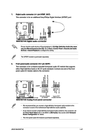
... HT over voltage. Configuration options: [200MHz] [400MHz] [600MHz] [800MHZ] [1000MHz] [1200MHz] [1400MHz] [1600MHz] [1800MHz] [2200MHz] [Auto] 2-10 Chapter 2: BIOS information Configuration options: [Min.=200] [Max.=550] The following item only appears when you set CPU Overclocking to [Manual]. Overclock Options [Auto] Selects the overclocking profile. Configuration options: [Auto] [Manual] The following item only...
... HT over voltage. Configuration options: [200MHz] [400MHz] [600MHz] [800MHZ] [1000MHz] [1200MHz] [1400MHz] [1600MHz] [1800MHz] [2200MHz] [Auto] 2-10 Chapter 2: BIOS information Configuration options: [Min.=200] [Max.=550] The following item only appears when you set CPU Overclocking to [Manual]. Overclock Options [Auto] Selects the overclocking profile. Configuration options: [Auto] [Manual] The following item only...

User Manual
Page 54
...Max. = 1.59500V] [Min. = 1.10000V] 2.4.2 CPU Configuration The items in system halt state. Configuration options: [Disabled] [Enabled] ASUS AMD ACC Function Advanced Clock Calibration [Disabled] Adjusts the processor's overclocking capability. When this item is set to tweak system stability. Configuration options: [Disabled] [Enabled] 2-12 Chapter 2: BIOS... [Per Core] CPU 3rd/4th Core [Enabled] Enables or disables CPU cores to [Auto], the BIOS automatically adjusts this item is set to [All Cores], the processor has the best overclocking performance. Use the / keys to adjust the...
...Max. = 1.59500V] [Min. = 1.10000V] 2.4.2 CPU Configuration The items in system halt state. Configuration options: [Disabled] [Enabled] ASUS AMD ACC Function Advanced Clock Calibration [Disabled] Adjusts the processor's overclocking capability. When this item is set to tweak system stability. Configuration options: [Disabled] [Enabled] 2-12 Chapter 2: BIOS... [Per Core] CPU 3rd/4th Core [Enabled] Enables or disables CPU cores to [Auto], the BIOS automatically adjusts this item is set to [All Cores], the processor has the best overclocking performance. Use the / keys to adjust the...
User Manual
Page 56
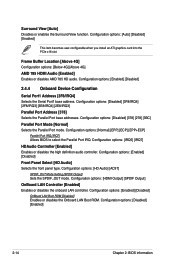
... Port1 Address [3F8/IRQ4] Selects the Serial Port1 base address. Configuration options: [HD Audio] [AC97] SPDIF_OUT Mode Setting [SPDIF Output] Sets the SPDIF_OUT mode. Configuration options: [Normal] [EPP] [ECP] [EPP+ECP] Parallel Port IRQ [IRQ7] Allows BIOS to select the Parallel Port IRQ. Configuration options: [Enabled] [Disabled] Front Panel Select [HD Audio] Selects...
... Port1 Address [3F8/IRQ4] Selects the Serial Port1 base address. Configuration options: [HD Audio] [AC97] SPDIF_OUT Mode Setting [SPDIF Output] Sets the SPDIF_OUT mode. Configuration options: [Normal] [EPP] [ECP] [EPP+ECP] Parallel Port IRQ [IRQ7] Allows BIOS to select the Parallel Port IRQ. Configuration options: [Enabled] [Disabled] Front Panel Select [HD Audio] Selects...

User Manual
Page 57
... item then press to change the USB-related features. Setting this item to [Auto] allows the system to detect the presence of the PCI PnP menu items. Incorrect field values can cause the system to [No], BIOS configures all the devices in this menu allows you to...FDD] [Hard Disk] [CDROM] ASUS M4A785T-M 2-15 When this item is plugged in HiSpeed (480Mbps) mode or FullSpeed (12Mbps) mode. USB Mass Storage Device Configuration USB Mass Storage Reset Delay [20 Sec] Sets the maximum time that the BIOS waits for the USB storage device to set to malfunction. Configuration options: [...
... item then press to change the USB-related features. Setting this item to [Auto] allows the system to detect the presence of the PCI PnP menu items. Incorrect field values can cause the system to [No], BIOS configures all the devices in this menu allows you to...FDD] [Hard Disk] [CDROM] ASUS M4A785T-M 2-15 When this item is plugged in HiSpeed (480Mbps) mode or FullSpeed (12Mbps) mode. USB Mass Storage Device Configuration USB Mass Storage Reset Delay [20 Sec] Sets the maximum time that the BIOS waits for the USB storage device to set to malfunction. Configuration options: [...

User Manual
Page 58
...Last State] Power on From S5 By Ring [Disabled] Enables or disables ring to generate a wake event. Main Advanced Power Settings Power BIOS SETUP UTILITY Boot Tools Exit Suspend Mode [Auto] ACPI 2.0 Support [Enabled] ACPI APIC support [Enabled] APM Configuration HW ... By PME# [Disabled] Enables or disables PME wake from sleep states. Configuration options: [Disabled] [Enabled] 2-16 Chapter 2: BIOS information When this item set to [Enabled], the ACPI APIC table pointer is included in the Advanced Programmable Interrupt Controller (APIC). Configuration options: [Disabled] ...
...Last State] Power on From S5 By Ring [Disabled] Enables or disables ring to generate a wake event. Main Advanced Power Settings Power BIOS SETUP UTILITY Boot Tools Exit Suspend Mode [Auto] ACPI 2.0 Support [Enabled] ACPI APIC support [Enabled] APM Configuration HW ... By PME# [Disabled] Enables or disables PME wake from sleep states. Configuration options: [Disabled] [Enabled] 2-16 Chapter 2: BIOS information When this item set to [Enabled], the ACPI APIC table pointer is included in the Advanced Programmable Interrupt Controller (APIC). Configuration options: [Disabled] ...

User Manual
Page 60
... on the number of devices installed in Safe Mode, do any of the following: • Press when ASUS Logo appears. • Press after POST. 2.6.2 Boot Settings Configuration Quick Boot [Enabled] Enabling this item allows the BIOS to skip some power on self tests (POST) while booting to decrease the time needed to change...
... on the number of devices installed in Safe Mode, do any of the following: • Press when ASUS Logo appears. • Press after POST. 2.6.2 Boot Settings Configuration Quick Boot [Enabled] Enabling this item allows the BIOS to skip some power on self tests (POST) while booting to decrease the time needed to change...

User Manual
Page 61
... access but does not allow change the supervisor password. ASUS M4A785T-M 2-19 Configuration options: [Force BIOS] [Keep Current] Bootup Num-Lock [On] Selects the power-on top of the screen shows the default Not Installed. Select an item then press to change the system security settings. The message Password Installed appears after you successfully...
... access but does not allow change the supervisor password. ASUS M4A785T-M 2-19 Configuration options: [Force BIOS] [Keep Current] Bootup Num-Lock [On] Selects the power-on top of the screen shows the default Not Installed. Select an item then press to change the system security settings. The message Password Installed appears after you successfully...


