
User Manual
Page 4
Contents 1.11 Software support 1-28 1.11.1 Installing an operating system 1-28 1.11.2 Support DVD information 1-28 Chapter 2: BIOS information 2.1 Managing and updating your BIOS 2-1 2.1.1 ASUS Update utility 2-1 2.1.2 ASUS EZ Flash 2 utility 2-2 2.1.3 ASUS CrashFree BIOS utility 2-3 2.2 BIOS setup program 2-4 2.2.1 BIOS menu screen 2-5 2.2.3 Navigation keys 2-5 2.2.2 Menu bar 2-5 2.2.4 Menu items 2-6 2.2.5 Submenu items 2-6 2.2.6 Configuration fields 2-6 2.2.7 Pop-up window 2-6 2.2.8 Scroll bar 2-6 2.2.9 General help 2-6 2.3 Main...
Contents 1.11 Software support 1-28 1.11.1 Installing an operating system 1-28 1.11.2 Support DVD information 1-28 Chapter 2: BIOS information 2.1 Managing and updating your BIOS 2-1 2.1.1 ASUS Update utility 2-1 2.1.2 ASUS EZ Flash 2 utility 2-2 2.1.3 ASUS CrashFree BIOS utility 2-3 2.2 BIOS setup program 2-4 2.2.1 BIOS menu screen 2-5 2.2.3 Navigation keys 2-5 2.2.2 Menu bar 2-5 2.2.4 Menu items 2-6 2.2.5 Submenu items 2-6 2.2.6 Configuration fields 2-6 2.2.7 Pop-up window 2-6 2.2.8 Scroll bar 2-6 2.2.9 General help 2-6 2.3 Main...
User Manual
Page 7
... About this guide is organized This guide contains the following parts: • Chapter 1: Product introduction This chapter describes the features of the BIOS parameters are not damaged. Do not place the product in your area. vii Detailed descriptions of the motherboard and the new technology it by...; When adding or removing devices to or from the system, ensure that your power supply is set to change system settings through the BIOS Setup menus. These devices could interrupt the grounding circuit. • Ensure that the power cables for the devices are unplugged before the ...
... About this guide is organized This guide contains the following parts: • Chapter 1: Product introduction This chapter describes the features of the BIOS parameters are not damaged. Do not place the product in your area. vii Detailed descriptions of the motherboard and the new technology it by...; When adding or removing devices to or from the system, ensure that your power supply is set to change system settings through the BIOS Setup menus. These devices could interrupt the grounding circuit. • Ensure that the power cables for the devices are unplugged before the ...
User Manual
Page 10
... 1 x 4-pin ATX 12V power connector BIOS ASUS special features ASUS overclocking features 8Mb Flash ROM, AMI BIOS, PnP, DMI2.0, WfM2.0, ACPI2.0a, SM BIOS 2.5 ASUS EPU-4 Engine ASUS Core Unlocker ASUS Anti-Surge Protection 100% All high quality conductive polymer capacitors (on M4N68T-M V2 only) ASUS Turbo Key ASUS Q-Fan ASUS EZ Flash 2 ASUS AI NET 2 ASUS MyLogo 2 ASUS Turbo Key SFS (Stepless Frequency Selection...
... 1 x 4-pin ATX 12V power connector BIOS ASUS special features ASUS overclocking features 8Mb Flash ROM, AMI BIOS, PnP, DMI2.0, WfM2.0, ACPI2.0a, SM BIOS 2.5 ASUS EPU-4 Engine ASUS Core Unlocker ASUS Anti-Surge Protection 100% All high quality conductive polymer capacitors (on M4N68T-M V2 only) ASUS Turbo Key ASUS Q-Fan ASUS EZ Flash 2 ASUS AI NET 2 ASUS MyLogo 2 ASUS Turbo Key SFS (Stepless Frequency Selection...
User Manual
Page 13
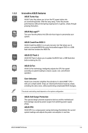
... a simple switch. After the easy setup, Turbo Key boosts performances without performing complicated BIOS changes. The actual overclocking result depends on the system configuration. ASUS M4N68T-M Series 1-3 ASUS CrashFree BIOS 3 ASUS CrashFree BIOS 3 is a unique power saving technology that contains the BIOS file. Core Unlocker ASUS Core Unlocker simplifies the activation of a latent AMD® CPU- Enjoy an instant...
... a simple switch. After the easy setup, Turbo Key boosts performances without performing complicated BIOS changes. The actual overclocking result depends on the system configuration. ASUS M4N68T-M Series 1-3 ASUS CrashFree BIOS 3 ASUS CrashFree BIOS 3 is a unique power saving technology that contains the BIOS file. Core Unlocker ASUS Core Unlocker simplifies the activation of a latent AMD® CPU- Enjoy an instant...
User Manual
Page 14
... the need to their default settings. Simply shut down and reboot the system, and the BIOS automatically restores the CPU parameters to open the system chassis and clear the RTC data. C.P.R. This is in line with the European Union's Restriction on ... products/packaging to safeguard consumers' health while minimizing the impact on the system and any faulty cable connections are reported back up to overclocking failure. ASUS AI NET2 ASUS AI NET2 remotely detects the cable connection immediately after you turn on the environment. 1-4 Chapter 1: Product introduction Green...
... the need to their default settings. Simply shut down and reboot the system, and the BIOS automatically restores the CPU parameters to open the system chassis and clear the RTC data. C.P.R. This is in line with the European Union's Restriction on ... products/packaging to safeguard consumers' health while minimizing the impact on the system and any faulty cable connections are reported back up to overclocking failure. ASUS AI NET2 ASUS AI NET2 remotely detects the cable connection immediately after you turn on the environment. 1-4 Chapter 1: Product introduction Green...
User Manual
Page 17
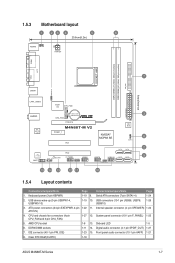
... 1-22 11. CPU and chassis fan connectors (4-pin CPU_FAN and 3-pin CHA_FAN) 1-27 12. Onboard LED 1-5 6. Clear RTC RAM (CLRTC) 1-18 ASUS M4N68T-M Series 1-7 Internal speaker connector (4- IDE connector (40-1 pin PRI_IDE) 1-23 15. pin SPEAKER) 1-24 ATX12V) 4. AMD CPU socket 1-8 13....6in) LAN1_USB12 Super I/O CPU_FAN EATXPWR Lithium Cell 3 AUDIO CMOS Power CHA_FAN RTL 8211CL -VB PCIEX16 M4N68T-M V2 PCIEX1_1 PCI1 NVIDIA® MCP68 SE 8Mb BIOS 8 CLRTC 2 SATA2 SATA4 PCI2 VIA VT1708S SB_PWR F_PANEL USB56 USB78 USB910 SATA1 SATA3 9 SPDIF_OUT SPEAKER ...
... 1-22 11. CPU and chassis fan connectors (4-pin CPU_FAN and 3-pin CHA_FAN) 1-27 12. Onboard LED 1-5 6. Clear RTC RAM (CLRTC) 1-18 ASUS M4N68T-M Series 1-7 Internal speaker connector (4- IDE connector (40-1 pin PRI_IDE) 1-23 15. pin SPEAKER) 1-24 ATX12V) 4. AMD CPU socket 1-8 13....6in) LAN1_USB12 Super I/O CPU_FAN EATXPWR Lithium Cell 3 AUDIO CMOS Power CHA_FAN RTL 8211CL -VB PCIEX16 M4N68T-M V2 PCIEX1_1 PCI1 NVIDIA® MCP68 SE 8Mb BIOS 8 CLRTC 2 SATA2 SATA4 PCI2 VIA VT1708S SB_PWR F_PANEL USB56 USB78 USB910 SATA1 SATA3 9 SPDIF_OUT SPEAKER ...
User Manual
Page 22
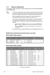
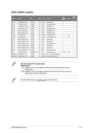
... of 3 ) 6144MB(Kit of 3) 6144MB(Kit of 3) 6144MB(Kit of the lower-sized channel for the dual-channel configuration. M4N68T-M Series Motherboard Qualified Vendors Lists (QVL) DDR3-1800(O.C.)MHz capability Vendor Part No. Size SS/DS Brand Chip NO. Timing DIMM...any of 2) SS Corsair CM3X2G1800C8D 2048MB DS Transcend TX1800KLU-2GK 1024MB SS N/A Heat-Sink Package N/A Heat-Sink Package N/A Heat-Sink Package Timing DIMM (BIOS) Voltage DIMM Support A* B* • • • • • DDR3-1600(O.C.)MHz capability Vendor A-Data Corsair Corsair Corsair Corsair Corsair ...
... of 3 ) 6144MB(Kit of 3) 6144MB(Kit of 3) 6144MB(Kit of the lower-sized channel for the dual-channel configuration. M4N68T-M Series Motherboard Qualified Vendors Lists (QVL) DDR3-1800(O.C.)MHz capability Vendor Part No. Size SS/DS Brand Chip NO. Timing DIMM...any of 2) SS Corsair CM3X2G1800C8D 2048MB DS Transcend TX1800KLU-2GK 1024MB SS N/A Heat-Sink Package N/A Heat-Sink Package N/A Heat-Sink Package Timing DIMM (BIOS) Voltage DIMM Support A* B* • • • • • DDR3-1600(O.C.)MHz capability Vendor A-Data Corsair Corsair Corsair Corsair Corsair ...
User Manual
Page 24
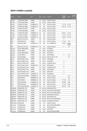
...-HCH9(ECC) 1024MB SS N/A Heat-Sink Package 1024MB SS N/A SEC 813HCH9 K4B1G0846D 1024MB SS N/A K4B1G0846D(ECC) 2048MB DS Micron 9GF27D9KPT 2048MB DS N/A SEC816HCH9K4B1G0846D Timing DIMM (BIOS) Voltage DIMM Support A* B* • •• 7-7-7-18 1.5~1.6V • • 9-9-9-24 1.5~1.6V • • •• • 8-8-8-21 1.5-1.6V • • 7-7-7-18 1.5~1.6V • •...
...-HCH9(ECC) 1024MB SS N/A Heat-Sink Package 1024MB SS N/A SEC 813HCH9 K4B1G0846D 1024MB SS N/A K4B1G0846D(ECC) 2048MB DS Micron 9GF27D9KPT 2048MB DS N/A SEC816HCH9K4B1G0846D Timing DIMM (BIOS) Voltage DIMM Support A* B* • •• 7-7-7-18 1.5~1.6V • • 9-9-9-24 1.5~1.6V • • •• • 8-8-8-21 1.5-1.6V • • 7-7-7-18 1.5~1.6V • •...
User Manual
Page 25
ASUS M4N68T-M Series 1-15 Crucial CT12864BA1067.8FF 1024MB SS Crucial CT12872BA1067.9FF 1024MB SS Crucial CT25664BA1067.16FF 2048MB DS Crucial CT25672BA1067.18FF 2048MB... Micron 9HF22D9KPT(ECC) Micron 8LD22D9JNL Micron 9HF22D9KPT Micron 9GF22D9KPT(ECC) N/A Heat-Sink Package Samsung SEC 901 HCF8 K4B1G0846E Samsung 846 K4B2G0846B-HCF8 Timing DIMM Voltage (BIOS) 7 7 7 7 7 1.5V 7 1.5V 7 7 7 7 7-7-7-16 1.75V DIMM Support A* B* • • • • • • • • • • • • • • • •...
ASUS M4N68T-M Series 1-15 Crucial CT12864BA1067.8FF 1024MB SS Crucial CT12872BA1067.9FF 1024MB SS Crucial CT25664BA1067.16FF 2048MB DS Crucial CT25672BA1067.18FF 2048MB... Micron 9HF22D9KPT(ECC) Micron 8LD22D9JNL Micron 9HF22D9KPT Micron 9GF22D9KPT(ECC) N/A Heat-Sink Package Samsung SEC 901 HCF8 K4B1G0846E Samsung 846 K4B2G0846B-HCF8 Timing DIMM Voltage (BIOS) 7 7 7 7 7 1.5V 7 1.5V 7 7 7 7 7-7-7-16 1.75V DIMM Support A* B* • • • • • • • • • • • • • • • •...
User Manual
Page 27
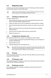
... your motherboard is completely seated on BIOS setup. 2. Replace the system cover. 1.8.2 Configuring an expansion card After installing the expansion card, configure it and make the necessary hardware settings for information on the slot. 5. See Chapter 2 for the card. 2. ASUS M4N68T-M Series 1-17 The following sub&#... that you removed earlier. 6. Install the software drivers for later use . When using PCI cards on the system and change the necessary BIOS settings, if any. Secure the card to the card. 3. Turn on shared slots, ensure that the drivers support "Share IRQ" or...
... your motherboard is completely seated on BIOS setup. 2. Replace the system cover. 1.8.2 Configuring an expansion card After installing the expansion card, configure it and make the necessary hardware settings for information on the slot. 5. See Chapter 2 for the card. 2. ASUS M4N68T-M Series 1-17 The following sub&#... that you removed earlier. 6. Install the software drivers for later use . When using PCI cards on the system and change the necessary BIOS settings, if any. Secure the card to the card. 3. Turn on shared slots, ensure that the drivers support "Share IRQ" or...
User Manual
Page 28
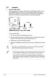
... battery powers the RAM data in CMOS. Turn OFF the computer and unplug the power cord. 2. Hold down and reboot the system so the BIOS can clear the CMOS memory of date, time, and system setup parameters by erasing the CMOS RTC RAM data. You can automatically reset parameter settings... to clear the Real Time Clock (RTC) RAM in CMOS, which include system setup information such as system passwords. CLRTC 12 23 M4N68T-M V2 Normal (Default) Clear RTC M4N68T-M Series Clear RTC RAM To erase the RTC RAM: 1. Removing the cap will cause system boot failure! • If the steps above ...
... battery powers the RAM data in CMOS. Turn OFF the computer and unplug the power cord. 2. Hold down and reboot the system so the BIOS can clear the CMOS memory of date, time, and system setup parameters by erasing the CMOS RTC RAM data. You can automatically reset parameter settings... to clear the Real Time Clock (RTC) RAM in CMOS, which include system setup information such as system passwords. CLRTC 12 23 M4N68T-M V2 Normal (Default) Clear RTC M4N68T-M Series Clear RTC RAM To erase the RTC RAM: 1. Removing the cap will cause system boot failure! • If the steps above ...
User Manual
Page 29
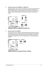
... setting in the BIOS. When you can supply at least 1A on the keyboard (the default is the Space Bar). This feature requires an ATX power supply that can wake up feature. KBPWR 12 23 +5V +5VSB (Default) M4N68T-M V2 M4N68T-M Series Keyboard Power Setting ASUS M4N68T-M Series 1-19 ...USBPW1-4 12 23 +5V +5VSB (Default) M4N68T-M V2 USBPW5-10 12 23 +5V +5VSB (Default) M4N68T-M Series USB Device Wake Up 3. Set these jumpers to +5V to...
... setting in the BIOS. When you can supply at least 1A on the keyboard (the default is the Space Bar). This feature requires an ATX power supply that can wake up feature. KBPWR 12 23 +5V +5VSB (Default) M4N68T-M V2 M4N68T-M Series Keyboard Power Setting ASUS M4N68T-M Series 1-19 ...USBPW1-4 12 23 +5V +5VSB (Default) M4N68T-M V2 USBPW5-10 12 23 +5V +5VSB (Default) M4N68T-M Series USB Device Wake Up 3. Set these jumpers to +5V to...
User Manual
Page 31
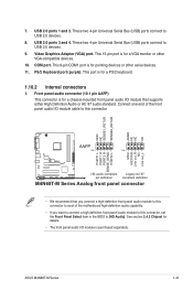
... item in the BIOS to USB 2.0 devices. 9. Front panel audio connector (10-1 pin AAFP) This connector is for a VGA monitor or other serial devices. 11. USB 2.0 ports 3 and 4. COM port. This 15-pin port is for pointing devices or other VGA-compatible devices. 10. PS/2 Keyboard port (purple). ASUS M4N68T-M Series 1-21 Connect...
... item in the BIOS to USB 2.0 devices. 9. Front panel audio connector (10-1 pin AAFP) This connector is for a VGA monitor or other serial devices. 11. USB 2.0 ports 3 and 4. COM port. This 15-pin port is for pointing devices or other VGA-compatible devices. 10. PS/2 Keyboard port (purple). ASUS M4N68T-M Series 1-21 Connect...
User Manual
Page 39
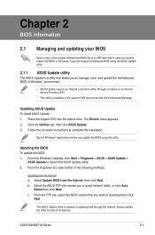
... tab, then click ASUS Update. 3. Select Update BIOS from the Internet a. c. b. Chapter 2 BIOS information 2.1 Managing and updating your BIOS Save a copy of the original motherboard BIOS file to a USB flash disk in case you need to restore the BIOS in the support DVD that comes with the motherboard package. ASUS M4N68T-M Series 2-1 Installing ASUS Update To install ASUS Update: 1. Follow...
... tab, then click ASUS Update. 3. Select Update BIOS from the Internet a. c. b. Chapter 2 BIOS information 2.1 Managing and updating your BIOS Save a copy of the original motherboard BIOS file to a USB flash disk in case you need to restore the BIOS in the support DVD that comes with the motherboard package. ASUS M4N68T-M Series 2-1 Installing ASUS Update To install ASUS Update: 1. Follow...
User Manual
Page 40
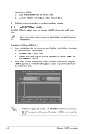
... then click Open. 3. Locate the BIOS file from a file, then click Next. EZ Flash 2 performs the BIOS updating process and automatically reboots the system when done. ASUSTek EZ Flash 2 BIOS ROM Utility V3.44 FLASH TYPE: WINBOND W25X80 Current ROM BOARD: M4N68T-M-V2 VER: 0303 (H:00 B:01) ...it. 2. b. Before you to complete the updating process. 2.1.2 ASUS EZ Flash 2 utility The ASUS EZ Flash 2 feature allows you start using this utility, download the latest BIOS file from a BIOS file a. Updating from the ASUS website at www.asus.com. Go to the Tools menu to select EZ Flash 2...
... then click Open. 3. Locate the BIOS file from a file, then click Next. EZ Flash 2 performs the BIOS updating process and automatically reboots the system when done. ASUSTek EZ Flash 2 BIOS ROM Utility V3.44 FLASH TYPE: WINBOND W25X80 Current ROM BOARD: M4N68T-M-V2 VER: 0303 (H:00 B:01) ...it. 2. b. Before you to complete the updating process. 2.1.2 ASUS EZ Flash 2 utility The ASUS EZ Flash 2 feature allows you start using this utility, download the latest BIOS file from a BIOS file a. Updating from the ASUS website at www.asus.com. Go to the Tools menu to select EZ Flash 2...
User Manual
Page 41
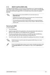
... NOT shut down or reset the system while updating the BIOS! ASUS M4N68T-M Series 2-3 When the BIOS file is an auto recovery tool that contains the updated BIOS file. • Before using this utility, rename the BIOS file in the removable device into M4N68TMV2.ROM. • The BIOS file in the support DVD may not be the...
... NOT shut down or reset the system while updating the BIOS! ASUS M4N68T-M Series 2-3 When the BIOS file is an auto recovery tool that contains the updated BIOS file. • Before using this utility, rename the BIOS file in the removable device into M4N68TMV2.ROM. • The BIOS file in the support DVD may not be the...

User Manual
Page 42
...system. Do this chapter are for this motherboard. 2-4 Chapter 2: BIOS information See section 2.8 Exit Menu. • The BIOS setup screens in using the first two options. Entering BIOS Setup at startup To enter BIOS Setup at www.asus.com to ensure optimum performance. Using the power button, reset button...only if you failed to your screen. • Visit the ASUS website at startup: • Press during the Power-On Self-Test (POST). Entering BIOS Setup after POST To enter BIOS Setup after changing any BIOS settings, load the default settings to turn the system off then...
...system. Do this chapter are for this motherboard. 2-4 Chapter 2: BIOS information See section 2.8 Exit Menu. • The BIOS setup screens in using the first two options. Entering BIOS Setup at startup To enter BIOS Setup at www.asus.com to ensure optimum performance. Using the power button, reset button...only if you failed to your screen. • Visit the ASUS website at startup: • Press during the Power-On Self-Test (POST). Entering BIOS Setup after POST To enter BIOS Setup after changing any BIOS settings, load the default settings to turn the system off then...
User Manual
Page 43
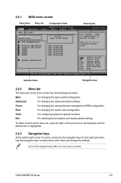
... For changing the advanced power management (APM) configuration Boot For changing the system boot configuration Tools For configuring options for that particular menu. ASUS M4N68T-M Series 2-5 Use [+] or [-] to another. Use the navigation keys to select a field. Select Screen Select Item +- To select ... key on top of the navigation keys differ from one screen to configure system Time. 2.2.1 BIOS menu screen Menu items Menu bar Configuration fields Main Advanced M4N68T-M-V2 BIOS Setup Power Boot Tools Exit Main Settings System Time [22:03:55] System Date [Mon ...
... For changing the advanced power management (APM) configuration Boot For changing the system boot configuration Tools For configuring options for that particular menu. ASUS M4N68T-M Series 2-5 Use [+] or [-] to another. Use the navigation keys to select a field. Select Screen Select Item +- To select ... key on top of the navigation keys differ from one screen to configure system Time. 2.2.1 BIOS menu screen Menu items Menu bar Configuration fields Main Advanced M4N68T-M-V2 BIOS Setup Power Boot Tools Exit Main Settings System Time [22:03:55] System Date [Mon ...
User Manual
Page 44
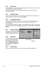
...and is a brief description of the field opposite the item. Press the / arrow keys or / keys to display a pop-up window Main Advanced M4N68T-M-V2 UTILITY Power Boot Tools Exit Select a menu item then press Suspend Mode ACPI 2.0 Support ACPI APIC support to display the other items (Advanced,... options for that do not fit on the screen. Select Screen Select Item +- To change the value of the selected item. 2-6 Chapter 2: BIOS information You cannot select an item that is user- configurable, you can change the value of a field, select it then press to RSDT pointer...
...and is a brief description of the field opposite the item. Press the / arrow keys or / keys to display a pop-up window Main Advanced M4N68T-M-V2 UTILITY Power Boot Tools Exit Select a menu item then press Suspend Mode ACPI 2.0 Support ACPI APIC support to display the other items (Advanced,... options for that do not fit on the screen. Select Screen Select Item +- To change the value of the selected item. 2-6 Chapter 2: BIOS information You cannot select an item that is user- configurable, you can change the value of a field, select it then press to RSDT pointer...
User Manual
Page 45
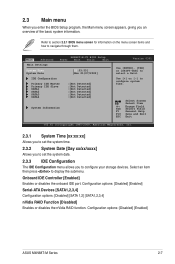
... system date. 2.3.3 IDE Configuration The IDE Configuration menu allows you an overview of the basic system information. Configuration options: [Disabled] [Enabled] ASUS M4N68T-M Series 2-7 2.3 Main menu When you enter the BIOS Setup program, the Main menu screen appears, giving you to navigate through them. Main Advanced Main Settings... M4N68T-M-V2 BIOS Setup Power Boot Tools Exit System Time [22:03:55] System Date [Mon 01/07/2002] IDE Configuration Primary IDE Master...
... system date. 2.3.3 IDE Configuration The IDE Configuration menu allows you an overview of the basic system information. Configuration options: [Disabled] [Enabled] ASUS M4N68T-M Series 2-7 2.3 Main menu When you enter the BIOS Setup program, the Main menu screen appears, giving you to navigate through them. Main Advanced Main Settings... M4N68T-M-V2 BIOS Setup Power Boot Tools Exit System Time [22:03:55] System Date [Mon 01/07/2002] IDE Configuration Primary IDE Master...


