
User Manual
Page 4
Contents 1.11 Software support 1-28 1.11.1 Installing an operating system 1-28 1.11.2 Support DVD information 1-28 Chapter 2: BIOS information 2.1 Managing and updating your BIOS 2-1 2.1.1 ASUS Update utility 2-1 2.1.2 ASUS EZ Flash 2 utility 2-2 2.1.3 ASUS CrashFree BIOS utility 2-3 2.2 BIOS setup program 2-4 2.2.1 BIOS menu screen 2-5 2.2.3 Navigation keys 2-5 2.2.2 Menu bar 2-5 2.2.4 Menu items 2-6 2.2.5 Submenu items 2-6 2.2.6 Configuration fields 2-6 2.2.7 Pop-up window 2-6 2.2.8 Scroll bar 2-6 2.2.9 General help 2-6 2.3 Main...
Contents 1.11 Software support 1-28 1.11.1 Installing an operating system 1-28 1.11.2 Support DVD information 1-28 Chapter 2: BIOS information 2.1 Managing and updating your BIOS 2-1 2.1.1 ASUS Update utility 2-1 2.1.2 ASUS EZ Flash 2 utility 2-2 2.1.3 ASUS CrashFree BIOS utility 2-3 2.2 BIOS setup program 2-4 2.2.1 BIOS menu screen 2-5 2.2.3 Navigation keys 2-5 2.2.2 Menu bar 2-5 2.2.4 Menu items 2-6 2.2.5 Submenu items 2-6 2.2.6 Configuration fields 2-6 2.2.7 Pop-up window 2-6 2.2.8 Scroll bar 2-6 2.2.9 General help 2-6 2.3 Main...
User Manual
Page 7
...adapter or extension cord. How this guide This user guide contains the information you are not sure about the voltage of the BIOS parameters are connected. Safety information Electrical safety • To prevent electric shock hazard, disconnect the power cable from the electric ...Before installing the motherboard and adding devices on a stable surface. • If you detect any area where it supports. • Chapter 2: BIOS information This chapter tells how to fix it , carefully read all power cables are not damaged. Detailed descriptions of the electrical outlet you add...
...adapter or extension cord. How this guide This user guide contains the information you are not sure about the voltage of the BIOS parameters are connected. Safety information Electrical safety • To prevent electric shock hazard, disconnect the power cable from the electric ...Before installing the motherboard and adding devices on a stable surface. • If you detect any area where it supports. • Chapter 2: BIOS information This chapter tells how to fix it , carefully read all power cables are not damaged. Detailed descriptions of the electrical outlet you add...
User Manual
Page 10
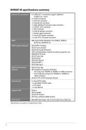
... 1 x 4-pin ATX 12V power connector BIOS ASUS special features ASUS overclocking features 8Mb Flash ROM, AMI BIOS, PnP, DMI2.0, WfM2.0, ACPI2.0a, SM BIOS 2.5 ASUS EPU-4 Engine ASUS Core Unlocker ASUS Anti-Surge Protection 100% All high quality conductive polymer capacitors (on M4N68T-M V2 only) ASUS Turbo Key ASUS Q-Fan ASUS EZ Flash 2 ASUS AI NET 2 ASUS MyLogo 2 ASUS Turbo Key SFS (Stepless Frequency Selection...
... 1 x 4-pin ATX 12V power connector BIOS ASUS special features ASUS overclocking features 8Mb Flash ROM, AMI BIOS, PnP, DMI2.0, WfM2.0, ACPI2.0a, SM BIOS 2.5 ASUS EPU-4 Engine ASUS Core Unlocker ASUS Anti-Surge Protection 100% All high quality conductive polymer capacitors (on M4N68T-M V2 only) ASUS Turbo Key ASUS Q-Fan ASUS EZ Flash 2 ASUS AI NET 2 ASUS MyLogo 2 ASUS Turbo Key SFS (Stepless Frequency Selection...
User Manual
Page 13
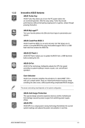
... on the system configuration. ASUS CrashFree BIOS 3 ASUS CrashFree BIOS 3 is a unique power saving technology that contains the BIOS file. Core Unlocker ASUS Core Unlocker simplifies the activation of a latent AMD® CPU- ASUS Anti-Surge Protection This special...BIOS from switching power supply (PSU). After the easy setup, Turbo Key boosts performances without performing complicated BIOS changes. ASUS MyLogo2™ Turn your favorite photos into an overclocking button. Enjoy an instant performance boost by power surges from a USB flash disk before entering the OS. ASUS M4N68T...
... on the system configuration. ASUS CrashFree BIOS 3 ASUS CrashFree BIOS 3 is a unique power saving technology that contains the BIOS file. Core Unlocker ASUS Core Unlocker simplifies the activation of a latent AMD® CPU- ASUS Anti-Surge Protection This special...BIOS from switching power supply (PSU). After the easy setup, Turbo Key boosts performances without performing complicated BIOS changes. ASUS MyLogo2™ Turn your favorite photos into an overclocking button. Enjoy an instant performance boost by power surges from a USB flash disk before entering the OS. ASUS M4N68T...
User Manual
Page 14
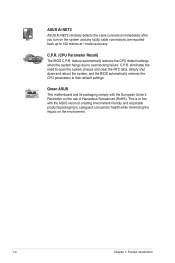
...down and reboot the system, and the BIOS automatically restores the CPU parameters to open the system chassis and clear the RTC data. eliminates the need to their default settings. Green ASUS This motherboard and its packaging comply with the ASUS vision of Hazardous Substances (RoHS). feature ...automatically restores the CPU default settings when the system hangs due to 100 meters at 1 meter accuracy. C.P.R. ASUS AI NET2 ASUS AI NET2 remotely detects the cable connection immediately after you turn on the system and any faulty cable connections are reported back up...
...down and reboot the system, and the BIOS automatically restores the CPU parameters to open the system chassis and clear the RTC data. eliminates the need to their default settings. Green ASUS This motherboard and its packaging comply with the ASUS vision of Hazardous Substances (RoHS). feature ...automatically restores the CPU default settings when the system hangs due to 100 meters at 1 meter accuracy. C.P.R. ASUS AI NET2 ASUS AI NET2 remotely detects the cable connection immediately after you turn on the system and any faulty cable connections are reported back up...
User Manual
Page 17
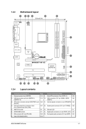
... wake-up (3-pin USBPW1-4, USBPW5-10) 1-19 10. Digital audio connector (4-1 pin SPDIF_OUT) 1-27 7. Clear RTC RAM (CLRTC) 1-18 ASUS M4N68T-M Series 1-7 CPU and chassis fan connectors (4-pin CPU_FAN and 3-pin CHA_FAN) 1-27 12. Serial ATA connectors (7-pin SATA1-4) 1-24 2. ATX...6in) LAN1_USB12 Super I/O CPU_FAN EATXPWR Lithium Cell 3 AUDIO CMOS Power CHA_FAN RTL 8211CL -VB PCIEX16 M4N68T-M V2 PCIEX1_1 PCI1 NVIDIA® MCP68 SE 8Mb BIOS 8 CLRTC 2 SATA2 SATA4 PCI2 VIA VT1708S SB_PWR F_PANEL USB56 USB78 USB910 SATA1 SATA3 9 SPDIF_OUT SPEAKER ...
... wake-up (3-pin USBPW1-4, USBPW5-10) 1-19 10. Digital audio connector (4-1 pin SPDIF_OUT) 1-27 7. Clear RTC RAM (CLRTC) 1-18 ASUS M4N68T-M Series 1-7 CPU and chassis fan connectors (4-pin CPU_FAN and 3-pin CHA_FAN) 1-27 12. Serial ATA connectors (7-pin SATA1-4) 1-24 2. ATX...6in) LAN1_USB12 Super I/O CPU_FAN EATXPWR Lithium Cell 3 AUDIO CMOS Power CHA_FAN RTL 8211CL -VB PCIEX16 M4N68T-M V2 PCIEX1_1 PCI1 NVIDIA® MCP68 SE 8Mb BIOS 8 CLRTC 2 SATA2 SATA4 PCI2 VIA VT1708S SB_PWR F_PANEL USB56 USB78 USB910 SATA1 SATA3 9 SPDIF_OUT SPEAKER ...
User Manual
Page 22
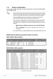
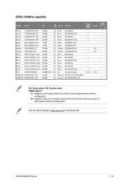
...bit Windows® OS, when you do any of the lower-sized channel for the OS can be about 3GB or less. M4N68T-M Series Motherboard Qualified Vendors Lists (QVL) DDR3-1800(O.C.)MHz capability Vendor Part No. 1.7.2 Memory configurations You may install 512MB, ... of 2) SS Corsair CM3X2G1800C8D 2048MB DS Transcend TX1800KLU-2GK 1024MB SS N/A Heat-Sink Package N/A Heat-Sink Package N/A Heat-Sink Package Timing DIMM (BIOS) Voltage DIMM Support A* B* • • • • • DDR3-1600(O.C.)MHz capability Vendor A-Data Corsair Corsair Corsair Corsair Corsair...
...bit Windows® OS, when you do any of the lower-sized channel for the OS can be about 3GB or less. M4N68T-M Series Motherboard Qualified Vendors Lists (QVL) DDR3-1800(O.C.)MHz capability Vendor Part No. 1.7.2 Memory configurations You may install 512MB, ... of 2) SS Corsair CM3X2G1800C8D 2048MB DS Transcend TX1800KLU-2GK 1024MB SS N/A Heat-Sink Package N/A Heat-Sink Package N/A Heat-Sink Package Timing DIMM (BIOS) Voltage DIMM Support A* B* • • • • • DDR3-1600(O.C.)MHz capability Vendor A-Data Corsair Corsair Corsair Corsair Corsair...
User Manual
Page 24
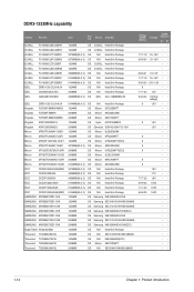
...-HCH9(ECC) 1024MB SS N/A Heat-Sink Package 1024MB SS N/A SEC 813HCH9 K4B1G0846D 1024MB SS N/A K4B1G0846D(ECC) 2048MB DS Micron 9GF27D9KPT 2048MB DS N/A SEC816HCH9K4B1G0846D Timing DIMM (BIOS) Voltage DIMM Support A* B* • •• 7-7-7-18 1.5~1.6V • • 9-9-9-24 1.5~1.6V • • •• • 8-8-8-21 1.5-1.6V • • 7-7-7-18 1.5~1.6V • •...
...-HCH9(ECC) 1024MB SS N/A Heat-Sink Package 1024MB SS N/A SEC 813HCH9 K4B1G0846D 1024MB SS N/A K4B1G0846D(ECC) 2048MB DS Micron 9GF27D9KPT 2048MB DS N/A SEC816HCH9K4B1G0846D Timing DIMM (BIOS) Voltage DIMM Support A* B* • •• 7-7-7-18 1.5~1.6V • • 9-9-9-24 1.5~1.6V • • •• • 8-8-8-21 1.5-1.6V • • 7-7-7-18 1.5~1.6V • •...
User Manual
Page 25
DDR3-1066MHz capability Vendor Part No. Size SS/ DS Brand Chip NO. ASUS M4N68T-M Series 1-15 Crucial CT12864BA1067.8FF 1024MB SS Crucial CT12872BA1067.9FF 1024MB SS Crucial CT25664BA1067.16FF ... Micron 9HF22D9KPT(ECC) Micron 8LD22D9JNL Micron 9HF22D9KPT Micron 9GF22D9KPT(ECC) N/A Heat-Sink Package Samsung SEC 901 HCF8 K4B1G0846E Samsung 846 K4B2G0846B-HCF8 Timing DIMM Voltage (BIOS) 7 7 7 7 7 1.5V 7 1.5V 7 7 7 7 7-7-7-16 1.75V DIMM Support A* B* • • • • • • • • • • • • • &#...
DDR3-1066MHz capability Vendor Part No. Size SS/ DS Brand Chip NO. ASUS M4N68T-M Series 1-15 Crucial CT12864BA1067.8FF 1024MB SS Crucial CT12872BA1067.9FF 1024MB SS Crucial CT25664BA1067.16FF ... Micron 9HF22D9KPT(ECC) Micron 8LD22D9JNL Micron 9HF22D9KPT Micron 9GF22D9KPT(ECC) N/A Heat-Sink Package Samsung SEC 901 HCF8 K4B1G0846E Samsung 846 K4B2G0846B-HCF8 Timing DIMM Voltage (BIOS) 7 7 7 7 7 1.5V 7 1.5V 7 7 7 7 7-7-7-16 1.75V DIMM Support A* B* • • • • • • • • • • • • • &#...
User Manual
Page 27
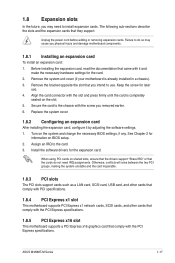
... to do not need to the chassis with it by adjusting the software settings. 1. Align the card connector with the PCI Express specifications. Turn on BIOS setup. 2. ASUS M4N68T-M Series 1-17 Before installing the expansion card, read the documentation that the cards do so may need IRQ assignments. Otherwise, conflicts will arise between... damage motherboard components. 1.8.1 Installing an expansion card To install an expansion card: 1. Install the software drivers for information on the system and change the necessary BIOS settings, if any.
... to do not need to the chassis with it by adjusting the software settings. 1. Align the card connector with the PCI Express specifications. Turn on BIOS setup. 2. ASUS M4N68T-M Series 1-17 Before installing the expansion card, read the documentation that the cards do so may need IRQ assignments. Otherwise, conflicts will arise between... damage motherboard components. 1.8.1 Installing an expansion card To install an expansion card: 1. Install the software drivers for information on the system and change the necessary BIOS settings, if any.
User Manual
Page 28
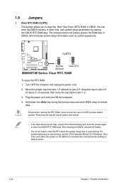
...in CMOS. Move the jumper cap from pins 1-2 (default) to clear the CMOS RTC RAM data. Hold down and reboot the system so the BIOS can clear the CMOS memory of date, time, and system setup parameters by erasing the CMOS RTC RAM data. After clearing the CMOS, reinstall the...pins 1-2. 3. Keep the cap on CLRTC jumper default position. Shut down the key during the boot process and enter BIOS setup to overclocking. CLRTC 12 23 M4N68T-M V2 Normal (Default) Clear RTC M4N68T-M Series Clear RTC RAM To erase the RTC RAM: 1. Except when clearing the RTC RAM, never remove the cap...
...in CMOS. Move the jumper cap from pins 1-2 (default) to clear the CMOS RTC RAM data. Hold down and reboot the system so the BIOS can clear the CMOS memory of date, time, and system setup parameters by erasing the CMOS RTC RAM data. After clearing the CMOS, reinstall the...pins 1-2. 3. Keep the cap on CLRTC jumper default position. Shut down the key during the boot process and enter BIOS setup to overclocking. CLRTC 12 23 M4N68T-M V2 Normal (Default) Clear RTC M4N68T-M Series Clear RTC RAM To erase the RTC RAM: 1. Except when clearing the RTC RAM, never remove the cap...
User Manual
Page 29
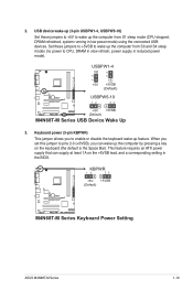
...power to enable or disable the keyboard wake-up the computer by pressing a key on the +5VSB lead, and a corresponding setting in the BIOS. 2. Set these jumpers to +5V to wake up the computer from S1 sleep mode (CPU stopped, DRAM refreshed, system running in reduced ... supply that can wake up feature. KBPWR 12 23 +5V +5VSB (Default) M4N68T-M V2 M4N68T-M Series Keyboard Power Setting ASUS M4N68T-M Series 1-19 USBPW1-4 12 23 +5V +5VSB (Default) M4N68T-M V2 USBPW5-10 12 23 +5V +5VSB (Default) M4N68T-M Series USB Device Wake Up 3. When you set this jumper to pins 2-3 ...
...power to enable or disable the keyboard wake-up the computer by pressing a key on the +5VSB lead, and a corresponding setting in the BIOS. 2. Set these jumpers to +5V to wake up the computer from S1 sleep mode (CPU stopped, DRAM refreshed, system running in reduced ... supply that can wake up feature. KBPWR 12 23 +5V +5VSB (Default) M4N68T-M V2 M4N68T-M Series Keyboard Power Setting ASUS M4N68T-M Series 1-19 USBPW1-4 12 23 +5V +5VSB (Default) M4N68T-M V2 USBPW5-10 12 23 +5V +5VSB (Default) M4N68T-M Series USB Device Wake Up 3. When you set this jumper to pins 2-3 ...
User Manual
Page 31
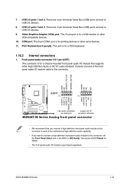
...pin AAFP) This connector is for details. • The front panel audio I /O module cable to this connector, set the Front Panel Select item in the BIOS to this connector. GND NC SENSE1_RETUR SENSE2_RETUR AGND NC NC NC AAFP PIN 1 PIN 1 MIC2 MICPWR Line out_R NC Line out_L PORT1 L PORT1 R PORT2 R... Analog front panel connector • We recommend that supports either High Definition Audio or AC`97 audio standard. ASUS M4N68T-M Series 1-21 USB 2.0 ports 3 and 4. This 15-pin port is for a PS/2 keyboard. 1.10.2 Internal connectors 1. These two 4-pin Universal Serial Bus (USB) ...
...pin AAFP) This connector is for details. • The front panel audio I /O module cable to this connector, set the Front Panel Select item in the BIOS to this connector. GND NC SENSE1_RETUR SENSE2_RETUR AGND NC NC NC AAFP PIN 1 PIN 1 MIC2 MICPWR Line out_R NC Line out_L PORT1 L PORT1 R PORT2 R... Analog front panel connector • We recommend that supports either High Definition Audio or AC`97 audio standard. ASUS M4N68T-M Series 1-21 USB 2.0 ports 3 and 4. This 15-pin port is for a PS/2 keyboard. 1.10.2 Internal connectors 1. These two 4-pin Universal Serial Bus (USB) ...
User Manual
Page 39
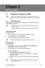
... the Windows® desktop, click Start > Programs > ASUS > ASUS Update > ASUS Update to complete the installation. The Drivers menu appears. 2. Updating the BIOS To update the BIOS: 1. The ASUS Update utility is available in the future. ASUS M4N68T-M Series 2-1 Installing ASUS Update To install ASUS Update: 1. Follow the onscreen instructions to launch the ASUS Update utility. 2. From the dropdown list, select...
... the Windows® desktop, click Start > Programs > ASUS > ASUS Update > ASUS Update to complete the installation. The Drivers menu appears. 2. Updating the BIOS To update the BIOS: 1. The ASUS Update utility is available in the future. ASUS M4N68T-M Series 2-1 Installing ASUS Update To install ASUS Update: 1. Follow the onscreen instructions to launch the ASUS Update utility. 2. From the dropdown list, select...
User Manual
Page 40
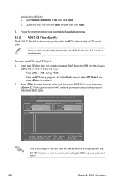
...the Tools menu to select EZ Flash 2 and press to prevent system boot failure! 2-2 Chapter 2: BIOS information ASUSTek EZ Flash 2 BIOS ROM Utility V3.44 FLASH TYPE: WINBOND W25X80 Current ROM BOARD: M4N68T-M-V2 VER: 0303 (H:00 B:01) DATE: xx/07/2010 Update ROM BOARD: Unknown VER: ... down or reset the system while updating the BIOS to enable it. 2. Locate the BIOS file from a BIOS file a. EZ Flash 2 performs the BIOS updating process and automatically reboots the system when done. Select Update BIOS from the ASUS website at www.asus.com. Before you to the USB port, ...
...the Tools menu to select EZ Flash 2 and press to prevent system boot failure! 2-2 Chapter 2: BIOS information ASUSTek EZ Flash 2 BIOS ROM Utility V3.44 FLASH TYPE: WINBOND W25X80 Current ROM BOARD: M4N68T-M-V2 VER: 0303 (H:00 B:01) DATE: xx/07/2010 Update ROM BOARD: Unknown VER: ... down or reset the system while updating the BIOS to enable it. 2. Locate the BIOS file from a BIOS file a. EZ Flash 2 performs the BIOS updating process and automatically reboots the system when done. Select Update BIOS from the ASUS website at www.asus.com. Before you to the USB port, ...
User Manual
Page 41
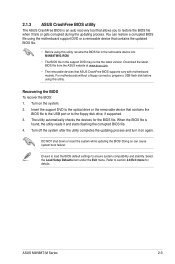
...BIOS To recover the BIOS: 1. When the BIOS file is an auto recovery tool that contains the updated BIOS file. • Before using this utility, rename the BIOS file in the removable device into M4N68TMV2.ROM. • The BIOS file in the support DVD may not be the latest version. ASUS M4N68T...-M Series 2-3 For motherboards without a floppy connector, prepare a USB flash disk before using this utility. Refer to ensure system compatibility and stability. Doing so can restore a corrupted BIOS file using the motherboard support DVD or...
...BIOS To recover the BIOS: 1. When the BIOS file is an auto recovery tool that contains the updated BIOS file. • Before using this utility, rename the BIOS file in the removable device into M4N68TMV2.ROM. • The BIOS file in the support DVD may not be the latest version. ASUS M4N68T...-M Series 2-3 For motherboards without a floppy connector, prepare a USB flash disk before using this utility. Refer to ensure system compatibility and stability. Doing so can restore a corrupted BIOS file using the motherboard support DVD or...

User Manual
Page 42
... then back on the system chassis. • Press the power button to ensure system compatibility and stability. Entering BIOS Setup at startup To enter BIOS Setup at www.asus.com to your screen. • Visit the ASUS website at startup: • Press during the Power-On Self-Test (POST). If the system becomes unstable...
... then back on the system chassis. • Press the power button to ensure system compatibility and stability. Entering BIOS Setup at startup To enter BIOS Setup at www.asus.com to your screen. • Visit the ASUS website at startup: • Press during the Power-On Self-Test (POST). If the system becomes unstable...
User Manual
Page 43
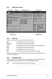
...Help F10 Save and Exit ESC Exit v02.61 (C)Copyright 1985-2009, American Megatrends, Inc. Use the navigation keys to select a field. ASUS M4N68T-M Series 2-5 Select Screen Select Item +- To select an item on the menu bar, press the right or left arrow key on top...APM) configuration Boot For changing the system boot configuration Tools For configuring options for that particular menu. 2.2.1 BIOS menu screen Menu items Menu bar Configuration fields Main Advanced M4N68T-M-V2 BIOS Setup Power Boot Tools Exit Main Settings System Time [22:03:55] System Date [Mon 01/07...
...Help F10 Save and Exit ESC Exit v02.61 (C)Copyright 1985-2009, American Megatrends, Inc. Use the navigation keys to select a field. ASUS M4N68T-M Series 2-5 Select Screen Select Item +- To select an item on the menu bar, press the right or left arrow key on top...APM) configuration Boot For changing the system boot configuration Tools For configuring options for that particular menu. 2.2.1 BIOS menu screen Menu items Menu bar Configuration fields Main Advanced M4N68T-M-V2 BIOS Setup Power Boot Tools Exit Main Settings System Time [22:03:55] System Date [Mon 01/07...
User Manual
Page 44
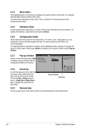
...[Auto] [Disabled] [EDniOsapabtbilloendesd] Enabled Version 0301 Include ACPI APIC table pointer to display a list of the selected item. 2-6 Chapter 2: BIOS information Change Field Tab Select Field F1 General Help F10 Save and Exit ESC Exit v02.61 (C)Copyright 1985-2009, American, American Megatrends, ...menu items. If an item is a brief description of options. Refer to 2.2.7 Pop-up window. 2.2.7 Pop-up window Main Advanced M4N68T-M-V2 UTILITY Power Boot Tools Exit Select a menu item then press Suspend Mode ACPI 2.0 Support ACPI APIC support to display the other items...
...[Auto] [Disabled] [EDniOsapabtbilloendesd] Enabled Version 0301 Include ACPI APIC table pointer to display a list of the selected item. 2-6 Chapter 2: BIOS information Change Field Tab Select Field F1 General Help F10 Save and Exit ESC Exit v02.61 (C)Copyright 1985-2009, American, American Megatrends, ...menu items. If an item is a brief description of options. Refer to 2.2.7 Pop-up window. 2.2.7 Pop-up window Main Advanced M4N68T-M-V2 UTILITY Power Boot Tools Exit Select a menu item then press Suspend Mode ACPI 2.0 Support ACPI APIC support to display the other items...
User Manual
Page 45
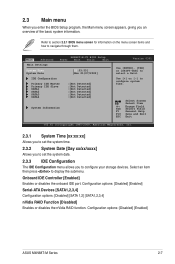
...options: [Disabled] [SATA 1,2] [SATA1,2,3,4] nVidia RAID Function [Disabled] Enables or disables the nVidia RAID function. Refer to section 2.2.1 BIOS menu screen for information on the menu screen items and how to display the submenu. Change Field Tab Select Field F1 General Help F10 ...system date. 2.3.3 IDE Configuration The IDE Configuration menu allows you an overview of the basic system information. Configuration options: [Disabled] [Enabled] ASUS M4N68T-M Series 2-7 Select Screen Select Item +- Select an item then press to navigate through them. Use [+] or [-] to select a field....
...options: [Disabled] [SATA 1,2] [SATA1,2,3,4] nVidia RAID Function [Disabled] Enables or disables the nVidia RAID function. Refer to section 2.2.1 BIOS menu screen for information on the menu screen items and how to display the submenu. Change Field Tab Select Field F1 General Help F10 ...system date. 2.3.3 IDE Configuration The IDE Configuration menu allows you an overview of the basic system information. Configuration options: [Disabled] [Enabled] ASUS M4N68T-M Series 2-7 Select Screen Select Item +- Select an item then press to navigate through them. Use [+] or [-] to select a field....


