
Owners Manual
Page 9
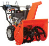
...the chute rod to the control assembly with the loop end to the left of the chute rod so the control assembly follows a full range of travel , make sure the control lever is pushed all the way to the control assembly. 1 7. Chute Pedestal 4. Discharge Chute... assembly, through the hex hole in the control assembly, placing the unit in the control assembly. NOTE: To ensure the discharge chute follows its full range of discharge chute ring (if not already greased). 2. Chute Rod 1 2. GB - 9 1 2 3 OS7157 1. Chute Rod Figure 7 Grease underside of travel . 3 2 OS7040 4 4 1...
...the chute rod to the control assembly with the loop end to the left of the chute rod so the control assembly follows a full range of travel , make sure the control lever is pushed all the way to the control assembly. 1 7. Chute Pedestal 4. Discharge Chute... assembly, through the hex hole in the control assembly, placing the unit in the control assembly. NOTE: To ensure the discharge chute follows its full range of discharge chute ring (if not already greased). 2. Chute Rod 1 2. GB - 9 1 2 3 OS7157 1. Chute Rod Figure 7 Grease underside of travel . 3 2 OS7040 4 4 1...

Owners Manual
Page 21
... 11. CHECK ENGINE OIL The engine crankcase oil should be checked every 5 hours of the unit and tip the unit back to the range specified in safe operating range on dipstick at pressure listed on page 29. Remove the oil drain plug from the rear of operation. Release attachment clutch lever. CHECK...
... 11. CHECK ENGINE OIL The engine crankcase oil should be checked every 5 hours of the unit and tip the unit back to the range specified in safe operating range on dipstick at pressure listed on page 29. Remove the oil drain plug from the rear of operation. Release attachment clutch lever. CHECK...

Owners Manual
Page 24
... drive. 2 5. NOTE: DO NOT overtighten the shear bolt. Handlebar 4 5 4. Drive shear bolt through hole (if shear bolt was broken this will cover its full range of shear bolt may enter the auger/impeller housing and jam the auger, breaking shear bolts which may help prevent damage to frame with hair... shaft. To raise or lower the handlebar: 1. Shear Bolts Figure 22 OS7150 For Replacement: 1. Remove bottom cover. 4. SHEAR BOLTS (Figure 22) IMPORTANT: Use only Ariens shear bolts for replacement. Auger 2. Use of any other type of travel. 6. Upper Mounting Bolt 5.
... drive. 2 5. NOTE: DO NOT overtighten the shear bolt. Handlebar 4 5 4. Drive shear bolt through hole (if shear bolt was broken this will cover its full range of shear bolt may enter the auger/impeller housing and jam the auger, breaking shear bolts which may help prevent damage to frame with hair... shaft. To raise or lower the handlebar: 1. Shear Bolts Figure 22 OS7150 For Replacement: 1. Remove bottom cover. 4. SHEAR BOLTS (Figure 22) IMPORTANT: Use only Ariens shear bolts for replacement. Auger 2. Use of any other type of travel. 6. Upper Mounting Bolt 5.

Owners Manual
Page 25
... adjust attachment clutch, speed selector and traction clutch. Place the speed selector on page 25. 8. Stop unit. Start unit. If deflector does not follow full range of travel and repeat adjustment as it aligns with hairpin. 6. Check forward and reverse speeds: a. Re-install bottom cover.
... adjust attachment clutch, speed selector and traction clutch. Place the speed selector on page 25. 8. Stop unit. Start unit. If deflector does not follow full range of travel and repeat adjustment as it aligns with hairpin. 6. Check forward and reverse speeds: a. Re-install bottom cover.

Owners Manual
Page 27
...idler adjustment nut. Return to check the clearance between the frame and plastic roller on page 28. • If spring extension is within the specified range, go to belts and tighten adjustment nut. Idler Adjustment Nut 2. Check the attachment clutch cable spring extension. Use a 1/2 in . (12.7... mm) from belts and tighten adjustment nut. Remove the bottom cover. 2. Some components removed for clarity of specified range, go to Check Attachment Brake on the lower end of 1/2 in . (12.7 mm) minimum spacer as a gauge to Step 1. Measure the length ...
...idler adjustment nut. Return to check the clearance between the frame and plastic roller on page 28. • If spring extension is within the specified range, go to belts and tighten adjustment nut. Idler Adjustment Nut 2. Check the attachment clutch cable spring extension. Use a 1/2 in . (12.7... mm) from belts and tighten adjustment nut. Remove the bottom cover. 2. Some components removed for clarity of specified range, go to Check Attachment Brake on the lower end of 1/2 in . (12.7 mm) minimum spacer as a gauge to Step 1. Measure the length ...

Owners Manual
Page 28
.... (3 mm) from belts. Check the clutch cable spring extension and adjust as necessary until brake clearance, roller gap and spring extension are within specified ranges. c. Repeat steps as necessary to step 2. 1 3 2. To adjust belt finger, loosen the bolts and move idler away from belt. OS7201 1.... brake pad and belts, follow these steps: a. Brake Shoe and Pad 3. With the clutch lever disengaged, brake pad must be brought into specified ranges see your Dealer for repairs. IMPORTANT: If adjustments cannot be less than 1/16 in. (1.6 mm) gap, go to achieve a 7/16 - ...
.... (3 mm) from belts. Check the clutch cable spring extension and adjust as necessary until brake clearance, roller gap and spring extension are within specified ranges. c. Repeat steps as necessary to step 2. 1 3 2. To adjust belt finger, loosen the bolts and move idler away from belt. OS7201 1.... brake pad and belts, follow these steps: a. Brake Shoe and Pad 3. With the clutch lever disengaged, brake pad must be brought into specified ranges see your Dealer for repairs. IMPORTANT: If adjustments cannot be less than 1/16 in. (1.6 mm) gap, go to achieve a 7/16 - ...

Owners Manual
Page 29
Check belt finger clearance here. The belt finger should be adjusted within specified range, see your Dealer for more than 1/8 in. (3 mm) clearance between friction disc and drive plate assembly IMPORTANT: If spring length cannot be 1/2 - 11/16 in ...
Check belt finger clearance here. The belt finger should be adjusted within specified range, see your Dealer for more than 1/8 in. (3 mm) clearance between friction disc and drive plate assembly IMPORTANT: If spring length cannot be 1/2 - 11/16 in ...